
Very Low Noise Pick-up Preamplifier

The trimmer resistor R1 and resistors A7/A8 are used to offset the tolerances of the A4 and A5 at the output of the differential amplifier. The transistor T4 and LED D1, along with the power source, are utilized to form the differential amplifier. The D1 is a flat red LED mounted on T4 for improved thermal coupling. Given the theoretical entry noise of around 0.4 nV/(Hz) (theoretical resistor value for 1Ω, Z), it is crucial to minimize the total noise. Thus, the impedance of the feedback circuit should be significantly less than 10 ohms. Conversely, the OR27 requires a specified minimum load impedance that should not fall below 600 ohms, implying that the feedback resistance must be less than 600 ohms. To maintain low prices for A9, a compromise must be made regarding the maximum gain, which is about 24 dB, or 15.7 times in this instance. An additional resistance, R11, placed before the feedback operational amplifier does not clutter the circuit while adding only 0.3 nV/(Hz)^(1/2) noise input, which, based on measured data, is 0.52 nV/(Hz)^(1/2). For higher profits, the input noise can be reduced to 0.4 nV/(Hz)^(1/2) by lowering the value of R9.
The preamplifier circuit utilizes a differential amplifier configuration to effectively amplify the small signals from moving coil cartridges. The use of three double-type transistors, arranged in a differential setup, allows for significant noise reduction due to the cancellation of common-mode noise. The choice of PNP transistors is particularly beneficial in this application, as their characteristics lend themselves to lower low-frequency noise, which is critical in high-fidelity audio applications.
The operational amplifier OR27 plays a crucial role in further amplification of the signal while maintaining low noise levels. The feedback network, carefully designed with resistors R1, A7, A8, and R11, ensures that the gain is controlled while minimizing additional noise contributions. The thermal coupling provided by the LED D1 mounted on T4 enhances the stability of the amplifier by improving heat dissipation, which is essential for maintaining consistent performance.
Furthermore, the design considers the impedance requirements of both the feedback circuit and the operational amplifier's load. By ensuring that the feedback impedance is significantly lower than the required load impedance of 600 ohms for OR27, the circuit achieves optimal performance without compromising on sound quality. The careful selection of components and their arrangement in the circuit is essential for achieving the desired low noise and high gain characteristics, making this preamplifier suitable for high-fidelity audio applications.The preamplifier was designed to signal sources such as low-impedance moving coil cartridges (MC) on turntables high fidelity (and yet still there). The impedance of the amplifier is 100 W. To keep the noise levels low, three double-type transistors MAT03 SSM2220 or linked together to form a differential amplifier.
Connecting this amp in front of an operand (OR27) is reduced to very low levels in noise input of the latter. The connections of the bases of the amplifier's inputs act as "super operator" very low noise input. One advantage of pnp transistors compared with the corresponding npn is much lower noise low frequencies.
On the other hand, creates a relatively high current polarization at the entrance, about 5.5 Ma, as effect of the regulation of 2 mA for each transistor in combination with the relatively low gain transistor pnp. The trimmer R 1 and resistance A7/A8 offset tolerances of the A4 and A5 at the exit of the differential amplifier. The tranxistor T4 LED D1 and the power source for forming the differential amplifier. The D1 is flat red LED's mounted on the T4 for better thermal coupling. Because thorythoW entry of the order of 0.4 nV / (Hz) (theoretical resistor value for 1I, Z) is an important feedback to grow as little as possible the total picture noise.
Therefore the impedance of the feedback circuit should be much less than 1O W. In contrast, one needs OR27 specified minimum load impedance that can not be less than 600 ohms, so the price feedback resistance is less than 600 W. To ensure low prices for the A9 should be someone compromise the value of the maximum gain (about 24 dB, or 15.7 times in our case).
Fitting extra resistance, R11, ahead of feedback operational amplifier that does not clutter while adding A9 only 0.3 nV / (Hz) 1 / 2 noise input, which in fact based on the measured data is 0.52 nV / (Hz) 1 / 2. If you want higher profits, can be image noise 0.4 nV / (Hz) 1 / 2 with a lower price for the R9.
Related Circuits
Line follower robots are commonly designed to follow a specific path on a track. Typically, these robots are controlled by microcontrollers; however, this article discusses a line follower robot designed without using a microcontroller. The assembly consists of three...
This device, available in a Stainless DIL 8 package, is capable of measuring four independent analog voltages ranging from 0 to 5 volts. It transmits the measurement results as four characters via a standard asynchronous serial link. The described device...
The next stage operates in conjunction with the first stage and is fully complementary. A cascode circuit is included to enhance the linearity of the amplifiers. This cascode circuit requires a constant reference voltage for biasing to activate the...
The circuit was designed to create a line preamplifier using double triode tubes. It consists of three parts, including the main preamplifier. The line preamplifier circuit utilizing double triode tubes is structured to enhance audio signals by amplifying low-level signals...
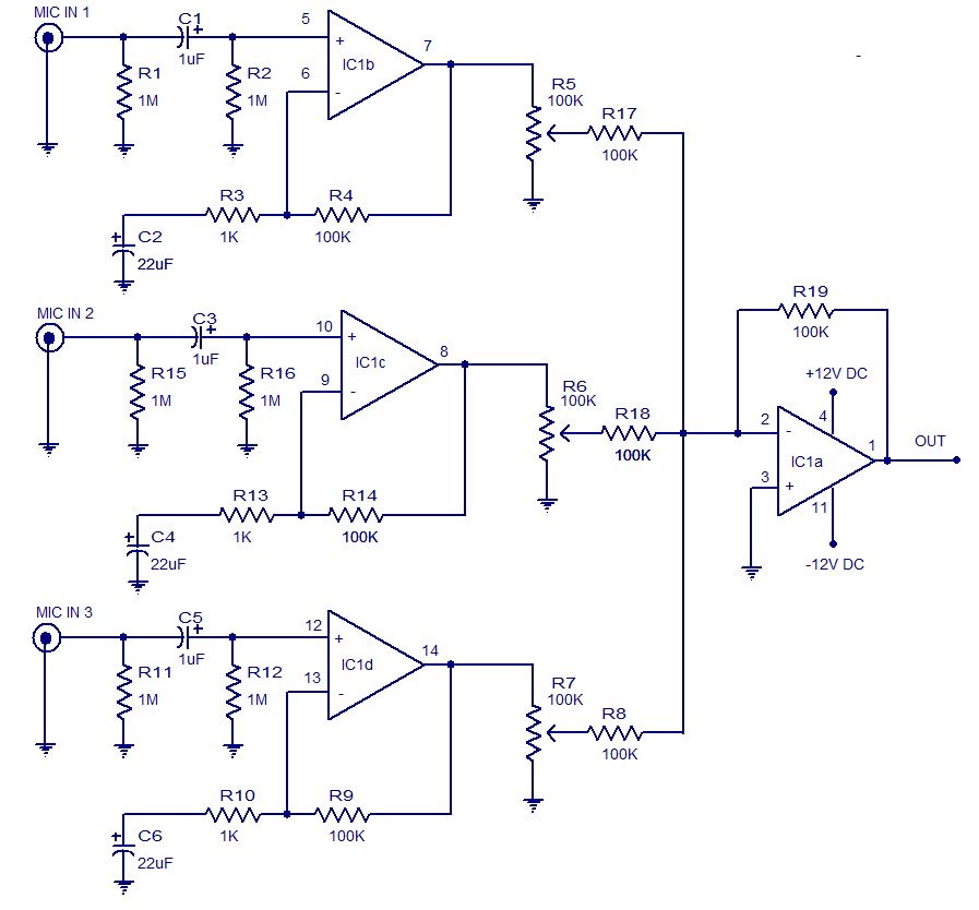
The circuit presented is a three-input microphone mixer and preamplifier utilizing the LM348 integrated circuit. The LM348 is a high-gain, internally compensated quad operational amplifier featuring a class AB output stage. It has a very low input supply current...
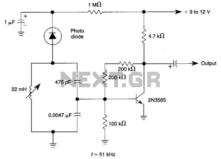
The circuit utilizes a tuned circuit for frequency selection, designed to operate at approximately 51 kHz. The 2N3565 transistor amplifies the output generated by the tuned circuit. The described circuit operates on the principle of resonance, where the tuned circuit...