
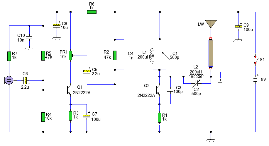
Mini FM Broadcast Transmitter

The mini FM transmitter circuit typically consists of several key components, including a microphone, an oscillator, a modulator, and an antenna. The microphone captures audio signals, which are then fed into the oscillator circuit. The oscillator generates a carrier frequency, which is modulated by the audio signal. This modulation process alters the amplitude of the carrier wave in accordance with the audio input, effectively encoding the sound information onto the radio frequency.
The circuit may utilize a simple transistor-based oscillator, which can be configured using common components such as resistors, capacitors, and inductors. The choice of transistor is crucial, as it must be capable of operating at the desired frequency range while providing sufficient gain to ensure effective transmission. A common configuration is the Colpitts or Hartley oscillator, which can produce stable oscillations necessary for FM transmission.
The modulated signal is then transmitted through an antenna, which should be designed to match the frequency of operation for optimal performance. The antenna can be a simple wire dipole or a more complex design, depending on the specific requirements of the project. The output power of the transmitter should be kept within legal limits to avoid interference with licensed broadcasts.
In addition to the basic components, the circuit may include various passive elements for filtering and stabilization, ensuring that the transmitted signal remains clean and free of distortion. Power supply considerations are also important, as the circuit must be powered adequately while minimizing noise introduced by the power source.
This mini FM transmitter project not only provides practical experience in circuit design and assembly but also offers insights into the principles of radio frequency communication, modulation techniques, and signal transmission. It serves as an excellent introduction to the field of electronics and wireless communication.Build your own simple mini FM transmitter. This fun project will show you how to build a mini broadcasting transmitter that can transmit an audio signal up to a quarter mile to any FM receiver. It`s easy to build and a good learning experience. It serves as a hands-on learning tool for students or anybody interested in electronics. Having a range of up to a quarter mile, it`s great for a house security system, baby monitoring device or simply a listening gadget that you can place anywhere!.
🔗 External reference
Related Circuits
The AM transmitter circuit consists of an audio amplifier and an RF oscillator. The oscillator is constructed around transistor Q1 and its associated components. The tank circuit, which includes inductor L1 and variable capacitor VC1, is tunable from approximately...
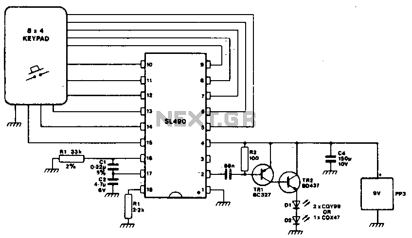
This simple infrared transmitter uses the PPM output from pin 2 of the SL490, which is connected to the base of the PNP transmitter TR1. It generates an amplified current pulse approximately 15 microseconds wide. This pulse is further...
An AM voice transmitter with variable tuning. The antenna circuit is also tuned and transmits via a long wire antenna. It is illegal to transmit on the AM wavebands in most countries; therefore, this circuit is provided for educational...
This circuit utilizes a 74HC14 hex Schmitt trigger inverter as a square wave oscillator to drive a small signal transistor configured in a class C amplifier setup. The frequency of the oscillator can be either fixed using a crystal...

The circuit design philosophy allows for debugging without any RF instruments. Although its performance may not match that of professional equipment, it should be adequate for hobbyists, with audio-visual transmission effects comparable to general-purpose machines. The transmitter consists of...
The RF oscillator employs inverter N2 and a 10.7 MHz ceramic filter to drive the parallel configuration of inverters N4 to N6 via N3. Due to the parallel arrangement of these inverters, the output impedance is low, allowing for...