
Mini Metronome

The circuit described utilizes transistors Q1 and Q2 to facilitate linear frequency modulation of the integrated circuit IC1. These transistors operate in a configuration that allows them to respond to changes in the resistance of potentiometer P1, effectively adjusting the frequency output of the metronome. The incorporation of Q3 enhances the audible click sound produced by the circuit, mimicking the auditory feedback of traditional mechanical metronomes, which is beneficial for musicians seeking a more pronounced auditory cue.
The power supply for this circuit is a 12V micro battery, chosen for its ability to deliver higher output power while maintaining a compact form factor. This choice of power supply is critical as it ensures that the circuit can operate efficiently without requiring excessive space, which is often a limitation in portable devices.
To adjust the tempo of the metronome, the user is instructed to rotate P1 fully towards R2, followed by an adjustment of resistor R1 to achieve a rhythm of 40 beats per minute. This setting can be verified by comparing it with another metronome to ensure accuracy. Conversely, when P1 is rotated fully towards R3, the user should adjust resistor R4 to achieve a tempo of 208 beats per minute. This range of settings allows for a versatile metronome capable of accommodating various musical styles and practice needs.
Finally, it is recommended to mark the entire scale of the potentiometer with the corresponding metronome steps, providing a clear reference for users to quickly select their desired tempo settings. This feature enhances usability, making the device more intuitive and accessible for musicians.Q1 & Q2 provide linear frequency operation of IC1 following P1 resistance variation. Q3 was added in order to obtain a louder click, similar to clockwork metronomes. A 12V micro battery was used to obtain a higher output power and more compactness. Rotate P1 fully towards R2, then set R1 to obtain 40 beats per minute (compare with another metronome). Rotate P1 fully towards R3, then set R4 to obtain 208 beats per minute. Finally mark the entire scale with the usual metronome steps, as follows: 🔗 External reference
Related Circuits
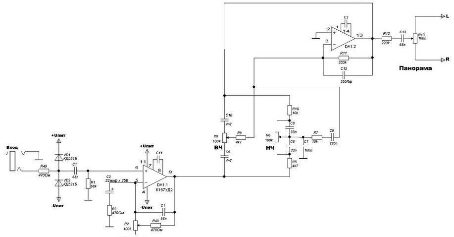
The four main input channels are identical and feature independently adjustable input sensitivity, tone, and sound panning. The fifth input is a linear channel. Despite its inexpensive and basic design, the Mini Audio Mixer "Impulse MM-04" performs satisfactorily. The Mini...
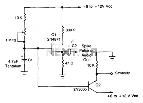
This simple oscillator utilizes a 2N4871 UJT to generate pulses ranging from 0.2 to approximately 20 Hz. A spike can be observed at C2, while a sawtooth waveform is present at the emitter of Q2, measuring about 2-3 V...
The LV2282VA is an FM Transmitter integrated circuit (IC). The multiplex (MPX) block generates a stereo modulated composite signal from left (L) and right (R) audio inputs. The radio frequency voltage-controlled oscillator (RF VCO) incorporates an FM modulation function....
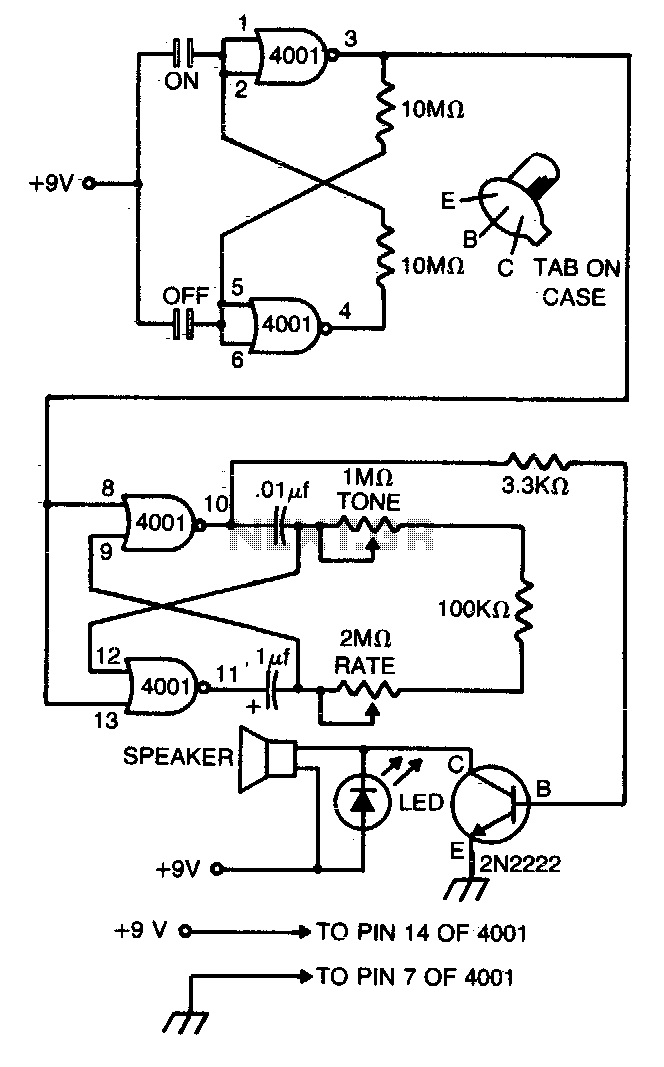
This compact metronome operates for years on a single nine-volt transistor battery. It features both tone and pulse rate controls and utilizes touch plates for starting and stopping. The device can be housed in a case no larger than...
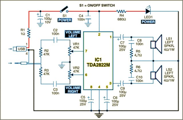
The circuit is designed as a dual audio power amplifier for use in battery-operated sound players. The TDA2822M specifications include low quiescent current, minimal crossover distortion, a supply voltage as low as 1.8 volts, and a minimum output power...
The circuit is designed to deliver approximately 10% distortion on a 4 Ohm to 8 Ohm loudspeaker. The LM4756 amplifier can output 7W of power. Utilizing four pairs of 2SC5200 and 2SA1943 transistors, this configuration can generate around 500W....