
mini projects

The circuit can also be adapted to illustrate basic traffic signaling principles, featuring red, yellow, and green lights, represented by LEDs. For effective operation, the lights of the same color on opposite roads must be synchronized to be ON or OFF simultaneously. In this model, the red light is designed to remain ON for 8 seconds, the yellow light for 8.2 seconds, and the green light for 10 seconds. The LEDs can be connected in series to manage current flow effectively, although parallel connections are possible, they are not preferred due to higher current demands on the integrated circuits. This design allows for a clear and efficient traffic signaling system that can be implemented in various applications.This circuit controls the switching of the street light or porch light and it will be automated. This circuit of automatic lamp controller using 7806 regulator IC can be used to automate street lights, tube lights or any other house electrical lightning systems. The IC 7806 is a voltage regulator IC that give a steady output voltage against widely fluctuating dc input voltage. For this IC, any voltage that appears in common terminal will be reflected at the output. So when the ground terminal is disconnected, the input is available at the output. When the common terminal is connected to the ground, the regulator output is equivalent to the rated voltage, and as soon as the terminal is disconnected from the ground, the output increases up to the input voltage. The common terminal is controlled by a transistor, which works as a switch on the terminal. For automatic control of light, a light-dependent resistor (LDR1) is connected to the base of the transistor.
In this way, the voltage regulator is able to operate a light bulb automatically as per the ambient light. To derive the power supply for the circuit, the 50Hz, 230V AC mains is stepped down by transformer X1 to deliver a secondary output of 12V, 250 mA.
The secondary output of the transformer is applied to a bridge rectifier comprising diodes D1 through D4, filtered by capacitor C1 and fed to the input terminal of the regulator (IC1). The common terminal (pin 2) of IC1 is connected to the ground line of the circuit through transistor BC557 (T1).
The transistor is biased by R2, R3, VR1 and LDR1. The grounding of IC1 is controlled by transistor T1, while light is sensed by LDR1. Using preset VR1, you can adjust the light-sensing level of transistor T1. The output of IC1 is fed to the base of transistor T2 (through resistor R4 and zener diode ZD1) and relay RL1. LED1 connected across the positive and ground supply lines acts as a power-on` indicator. Normally, the resistance of LDR1 is low during daytime and high during nighttime. During daytime, when light falls on LDR1, pnp transistor T1 conducts. The common terminal of IC1 connects to the ground and IC1 outputs 6V. As a result, transistor T2 does not conduct and the relay remains de-energized. The light bulb remains off` as the mains connection is not completed through the relay contacts. During nighttime, when no light falls on LDR1, it offers a high resistance at the base junction of transistor T1.
So the bias is greatly reduced and T1 doesn`t conduct. Effectively, this removes the common terminal of IC1 from ground and it directs the full input DC to the output. Transistor T2 conducts and the relay energizes to light up the bulb as mains connection completes through the relay contacts.
As LDR1 is in parallel to VR1+R3 combination, it effectively applies only half of the total resistance of the network formed by R3, VR1 and LDR1 to the junction at T1 in total darkness. In bright light, it greatly reduces the total effective resistance at the junction. The circuit is simple and can be assembled on a small general-purpose PCB. Use a heat-sink for IC1. Make sure that LDR1 and the light bulb are well separated. The circuit can be used for streetlights, tube lights or any other home electrical lighting system that needs to be automated.
· A simple circuit to illustrate the basic principles of traffic signaling is presented here. A typical road-crossing provided with red yellow and green lights. These lights are stimulated by LEDs. It is known that the lights of same color on the opposite roads will have to be ON or OFF simultaneously. Thus base on LED are connected in series (though they could be wired in parallel, it is not preferred because of higher current demand on ICs.
). For the purpose of this model. It has been assumed that red light will be ON for 8 seconds (or 8 units of time ), the yellow light will be ON for 8 2 seconds and green lights for 10 secs i 🔗 External reference
Related Circuits
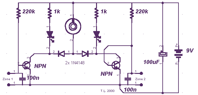
A few months ago, I decided to build a compact, yet effective alarm. My demands were: simple construction, reliable operation, very small power consumption, and, most of all, small size. I started with CMOS logic gates, but was soon...
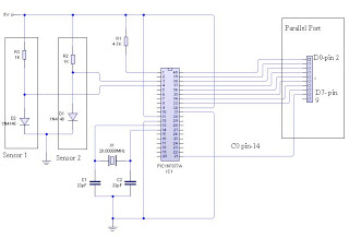
The dual-channel thermometer is a simple project based on a PIC microcontroller with ADC capabilities. It is an inexpensive thermometer that utilizes low-cost components and does not require high-sensitivity or expensive sensors. Instead, it employs a simple silicon diode...
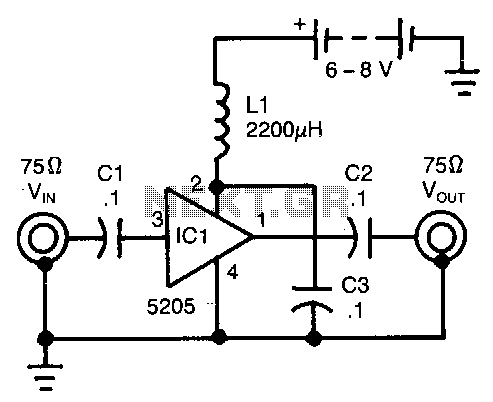
This wideband amplifier utilizes only five components. External signals are introduced to pin 3 of IC1 through an AC coupling capacitor, C1. After amplification, the enhanced signals from pin 1 of IC1 are transmitted to the output via capacitor...
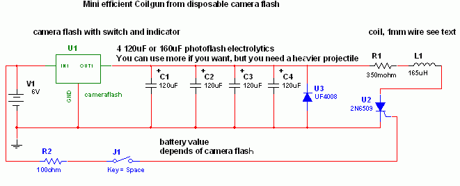
This is a fun and non-dangerous project for individuals interested in launching projectiles using magnetic forces. The mechanism operates by positioning a ferromagnetic projectile at one end of a coil and applying a power pulse. The critical aspect is...
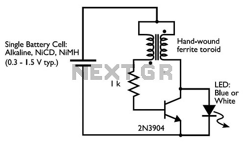
Drive a blue or white LED from a low voltage. Typically, lighting a blue or white LED requires a voltage of 3 to 3.5 V, which can be supplied by a 3 V lithium coin cell. However, a 1.5...
Nowadays, every institution requires automation. As part of college automation, a project has been developed titled "Voice Interactive System for College Automation." This project enables users to quickly access student attendance and marks through a telephone line without the...