
Mini Voice Operated Relay

The voice-operated relay circuit typically consists of several key components, including a microphone, an operational amplifier (op-amp), a comparator circuit, a relay, and associated resistors and capacitors. The microphone detects sound waves and converts them into an electrical signal. This signal is then amplified by the op-amp to ensure that it is strong enough for further processing.
The amplified signal is fed into a comparator circuit, where it is compared against a predefined threshold voltage. This threshold is set to distinguish between background noise and significant sound events, ensuring that only intentional sound inputs (such as a clap or voice command) trigger the relay. If the input signal exceeds the threshold, the comparator outputs a high signal, activating the relay.
The relay acts as a switch, controlling the flow of AC power to a connected load, such as a lamp or other electrical appliance. The circuit can be designed to toggle the relay state with each qualifying sound input, providing a convenient method for controlling devices without physical interaction.
Additional components, such as diodes, may be included to protect the circuit from voltage spikes caused by the relay's inductive load. A power supply circuit is also necessary to provide the required operating voltage for the microphone, op-amp, and relay. Overall, this circuit offers an innovative solution for sound-activated control in various applications, enhancing convenience and accessibility.This is the circuit diagram of a voice operated relay. It similar with sound activation switch circuit which will turn on and turn off (connect and disconnect) the switch depending on the sound input. The output switch of this circuit is ac.. 🔗 External reference
Related Circuits
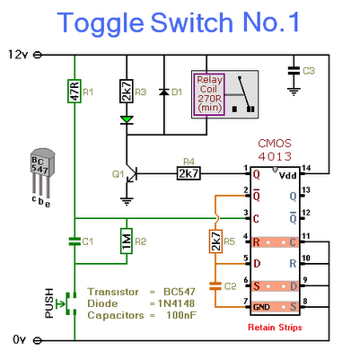
This circuit will activate and deactivate a relay with the press of a button. Any momentary push-to-make switch can be utilized. Pressing the button once will activate the relay, while pressing it a second time will deactivate the relay....
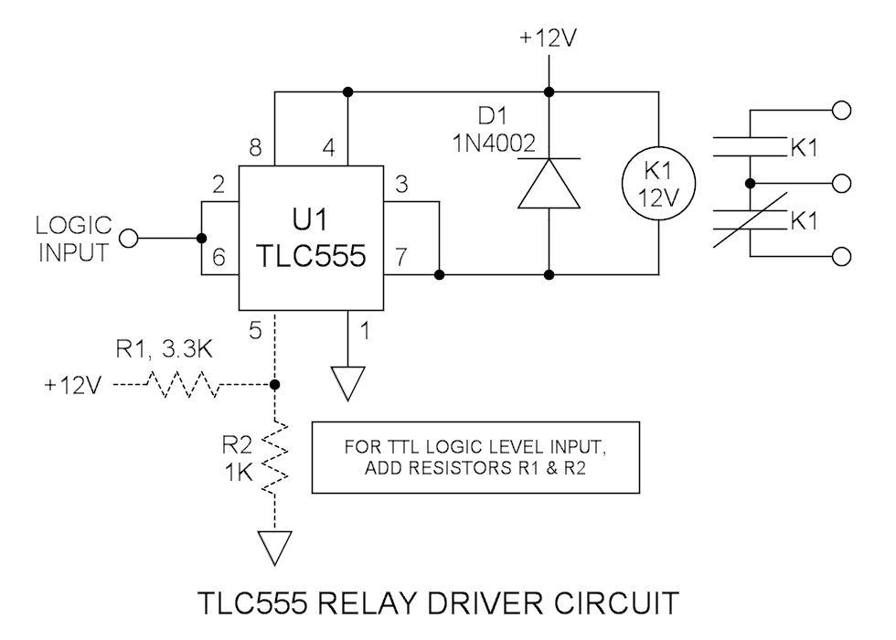
Many integrated circuits possess undocumented features or capabilities. The TLC555 output (pin 3) can sink a load of 100mA down to 1.28V. The open-drain transistor reset (pin 7) can also sink 100mA to 1V. Connecting both lines is permissible...
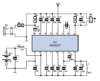
Several integrated circuits (ICs) are currently available that provide a nearly complete FM receiver solution. This project outlines a complete FM receiver circuit that offers excellent receiving and sound qualities. However, from a DIY enthusiast's perspective, the only drawback...
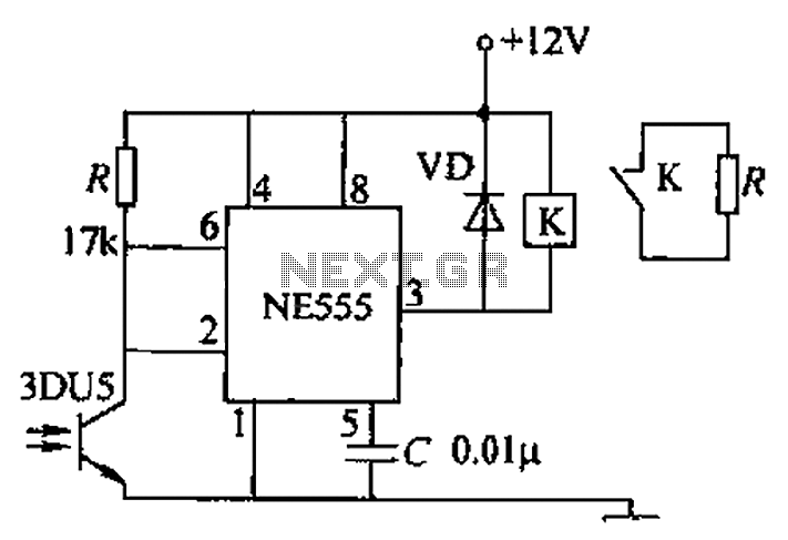
A transmitting circuit powered by an infrared light-emitting diode emits light. The receiving circuit, shown in the figure, utilizes a transistor (3DU5) to receive the infrared light and output the received signal. The signal is sent to terminal 3...
This is a power-on time delay relay circuit that utilizes the emitter/base breakdown voltage of a standard bipolar transistor. The reverse-connected emitter/base junction of a 2N3904 transistor functions as an 8-volt zener diode, establishing a higher turn-on voltage for...
A simplified block diagram of the MiniLOGGER is presented. The CMOS analog multiplexer, 4051, provides output for an 8-channel single-ended input to the analog-to-digital converter chip, CA3162, which operates in free-running mode. The digital output is a 4-bit BCD...