Minimum-component-flasher

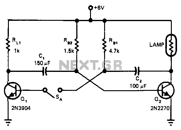
Opening SA changes the indicator lamp from a flashing to a steady-lit condition. The 6-V incandescent lamp on the collector of Q2 requires about 0.3 A. A 1 kΩ load resistor limits Q1's collector current to about 6 mA. The circuit is, therefore, asymmetrical with respect to the on currents of the transistors, allowing the use of a much smaller transistor for Q1 than for Q2.
The described circuit utilizes two transistors, Q1 and Q2, to control the operation of an indicator lamp. When switch SA is opened, the circuit transitions from a flashing state to a steady state, indicating a change in the operational status. The lamp, rated at 6 volts, draws a current of approximately 0.3 A when fully operational. This current is sufficient to illuminate the lamp steadily, providing clear visual feedback.
To manage the current through Q1, a load resistor of 1 kΩ is employed, which limits the collector current of Q1 to around 6 mA. This design choice is crucial as it ensures that Q1 operates within safe limits while still effectively controlling the operation of Q2. The asymmetrical nature of the circuit allows for a smaller transistor to be used for Q1 compared to Q2, optimizing component size and potentially reducing costs without sacrificing performance.
In practical applications, this configuration can be particularly useful in indicator circuits where power consumption needs to be minimized while still providing reliable operation. The choice of a 1 kΩ resistor is a balance between ensuring adequate current flow to activate Q1 and preventing excessive current that could lead to overheating or damage. The overall design demonstrates a thoughtful approach to transistor selection and circuit configuration, ensuring efficiency and functionality in the intended application.Opening SA, changes the indicator lamp from flashing to steady-lit condition. The 6-V incandescent lamp on the collector of Q2 requires about 0.3 A. A 1-KO load resistor limits Ql"s collector current to about 6 mA. The circuit is, therefore, asymmetrical with respect to the on currents of the transistors, allowing use of a much smaller transistor for Ql than for Q2.