
Misc. Circuits

The described touch sensor circuit is designed to detect physical touch through a capacitive sensing mechanism. It operates by measuring changes in capacitance caused by the proximity of a conductive object, such as a finger, to the metal touch plate. The circuit consists of a capacitive touch plate connected to pin P1, which serves as the input for the sensor. The digital output is available on pin P2, providing a high or low signal based on the detected touch.
To optimize the sensitivity of the touch sensor, a variable resistor is included in the circuit. This resistor allows for fine-tuning of the sensor's responsiveness to touch, accommodating different environmental conditions and the physical characteristics of the touch plate. While a standard value of 200k ohms has been noted as effective, it is essential to experiment with different resistor values to achieve the desired sensitivity for specific applications.
In practical applications, this touch sensor can be integrated into various electronic projects beyond its initial design for a cymbal mute sensor. It can be utilized in interactive installations, touch-sensitive lighting controls, or as a simple switch in hobbyist electronics. The provided KiCad files facilitate easy modifications and adaptations for specific project needs, enabling users to customize the circuit layout and component values as required.
Overall, this touch sensor circuit exemplifies versatility in electronic design, providing a foundation for various creative applications while allowing for user-specific adjustments to enhance performance.Included on this page are various small circuits I have created over time. Some are trivial, some are a bit more complex, but hopefully all are useful in a variety of projects. Most include both the schematics as well as the source ( KiCad ) files. This is a touch sensor with adjustable sensitivity, which will output a digital signal specfying whe ther or not it is being touched. I originally created it as a cymbal mute sensor for my electronic drum hardware, although it could be used for any sort of touch sensitive switch. You would connect the metal touch plate to P1; the digital output is on P2. The exact value of the variable resistor will differ based on conditions, size of capacitance touch plate, etc; 200k seems to work for me, but you may need to adjust this a bit.
🔗 External reference
Related Circuits
This circuit operates on 12V DC instead of mains AC. This is an advantageous approach for those who prefer not to deal with circuits connected directly to mains voltage or wish to power the stroboscope using batteries. Flash Slave...

This is a simple and cost-effective solar battery charger that can be constructed by hobbyists. It has some limitations compared to other similar controllers, but it also provides several benefits. While primarily designed for charging lead-acid batteries, it can...

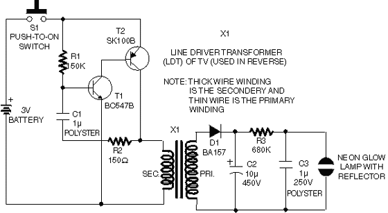
This is an analog TV transmitter. Sound modulation is of the FM type with a 5.5 MHz carrier frequency, and video transmission follows the PAL standard. The frequency can be adjusted using capacitor C5, allowing tuning from 54 to...
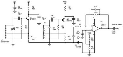
One type of metal detector is a beat frequency oscillator (BFO). The operation of metal detectors relies on changing the characteristics of the oscillator when it is near a metal object detected by the sensor. The detector functions based...

The circuit described is a crystal oscillation circuit using a CM OS inverting configuration, designed to ensure accurate operation. It employs a BCD counter (IC2) capable of achieving a maximum oscillation frequency of 2 MHz, which is 100 times...
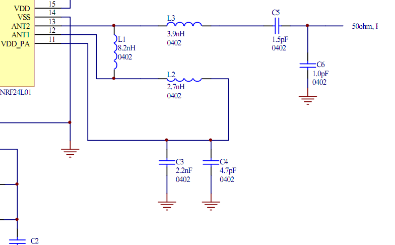
Place the transceiver and the chip antenna very close together, eliminating the need for a 50-ohm transmission line. If this is the case, can the two matching circuits be merged into one to reduce the component count? To create an...