
Moisture Detector Circuit

The moisture detector circuit operates based on the interaction between two PNP transistors and a piezoelectric transducer, which is critical for sound generation. The first transistor, Q1, acts as a crystal-controlled oscillator, utilizing a segment of the piezoelectric transducer that is divided into two crystal regions. The smaller crystal region is specifically designed to set the frequency of the oscillator, while the larger region is responsible for generating the audible alarm tone when activated.
The piezoelectric transducer is configured with three leads: two leads are dedicated to the individual crystals, and the third lead serves as a common ground. This arrangement allows for efficient signal processing and sound production. When water is detected, it acts as a resistor in the circuit, effectively providing the necessary bias to turn on transistor Q2. This switching action is crucial, as Q2 must be in an active state to enable Q1 to function properly.
When water contacts the probe, the resistance changes, allowing current to flow from the collector of Q2 to its base. This negative bias energizes Q2, allowing it to conduct and subsequently energize Q1. Once Q1 is activated, it drives the larger piezoelectric crystal, resulting in the emission of a loud sound from the transducer. This sound serves as an alarm, indicating the presence of moisture.
The design of the moisture detector circuit emphasizes the importance of component interaction and biasing techniques in achieving reliable operation. The use of piezoelectric materials not only facilitates sound production but also enhances the sensitivity of the moisture detection mechanism. Overall, this circuit provides an effective solution for moisture detection applications, leveraging the properties of transistors and piezoelectric devices to create a functional alarm system. The moisture detector uses two transistors and a piezoelectric transducer to sound an alarm tone when water is present. Transistor Ql forms a crystal-controlled oscillator, using a portion of piezoelectric transducer XDCwhich contains two piezoelectric crystal regionsas the crystal.
The transducer has three separate leads. One lead goes to each of the crystals, and the third lead is common to both. The smaller internal crystal region sets the frequency of operation and the larger element is driven by Ql (when it is biased on) to provide the loud tone output. To turn the pnp transistor Ql (used as an oscillator) on pnp transistor Q2 (used here as a switch) must be on. To turn it on with the biasing that is normally connected, you would only need to connect a resistor from the collector of Q2 to the base, which gives the base a negative (-) bias.
The resistor used is the water that is to be detected. That turns Q2 on, which, in turn, turns on Ql. The result when water touches the probe is that the transducer emits a loud sound.
Related Circuits
This oscillator is a variation of the oscillator presented by Ulrich L. Rohde, DJ2LR, in his article "Evaluating Noise Sideband Performance in Oscillators," published in Ham Radio, October 1978, Page 51. The original circuit can be found at the...
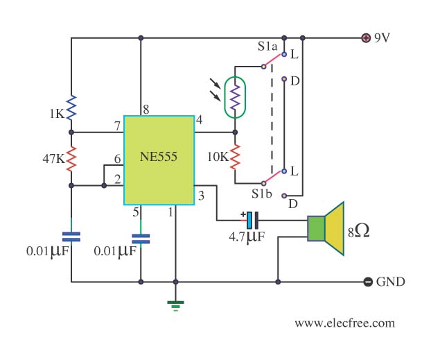
This circuit detects light and provides a voice warning. It responds to changes in light conditions, becoming active based on the position of switch S1. The circuit utilizes a light-dependent resistor (LDR) to sense ambient light levels. When the light...
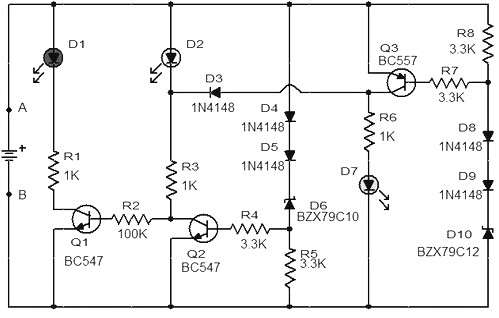
When the battery voltage is 11.5V or less, transistor Q1 is activated, and LED D1 will illuminate. When the battery voltage is between 11.5V and 13.5V, transistor Q2 is activated, causing LED D2 to light up. At a battery...
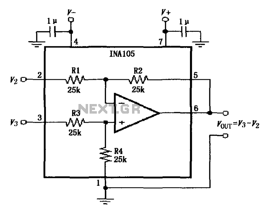
The power supply terminal should utilize a 1 µF chip capacitor filter, positioned as close as possible to the chip's supply pin. The signal is generated by the input pins 2 and 3. The source resistance of the signal...
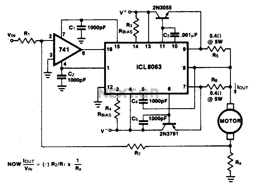
This minimum device circuit can be used to drive DC motors where there is some likelihood of stalling or lock-up. If the motor locks, the current drive remains constant, and the system does not destroy itself. This circuit is designed...
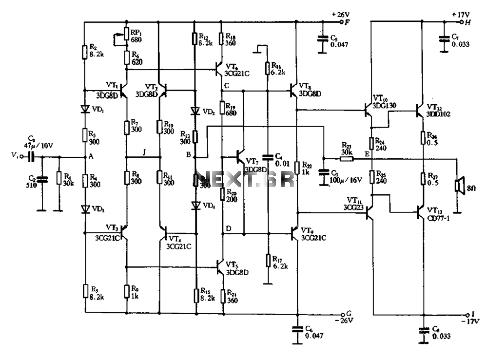
Almost all DC amplifier circuits are utilized as the input stage of differential circuits. Many complementary symmetry circuits also employ a double differential complementary sub-circuit along with a constant current source for the input stage. The constant current source...