
Mole Deterrent Teardown
A healthy population of moles exists in the vicinity, prompting the purchase of four inexpensive ultrasonic mole deterrents from eBay to encourage them to relocate. The devices emit a frequency that is unpleasant to moles, leading them to vacate the area. Some products are labeled as ultrasonic mole deterrents, while others simply refer to sonic mole deterrents. The distinction between sonic and ultrasonic lies in the frequency range, with ultrasonic being above the human hearing range (approximately 20 kHz). The purchased model did not function long enough to determine its effectiveness fully, but initial observations suggested some impact. The circuit design utilizes 2N2222 and 2N907 transistors in LTSpice simulations, as models for the actual components (9014 or S8550) are not available. The circuit operates with Q1 and Q3 controlling on/off pulses, with a capacitor charging and discharging to generate sound through a buzzer. The simulation results showed waveforms consistent with expected behavior. The buzzer construction involves a resistor, a transistor, a magnet, and a coil, creating a blocking oscillator that produces sound. However, the actual parts used may differ from those in the simulation. The design is not robust enough for outdoor use, as evidenced by the failure of all four units within months, primarily due to poor adhesive on the magnet and inadequate weatherproofing.
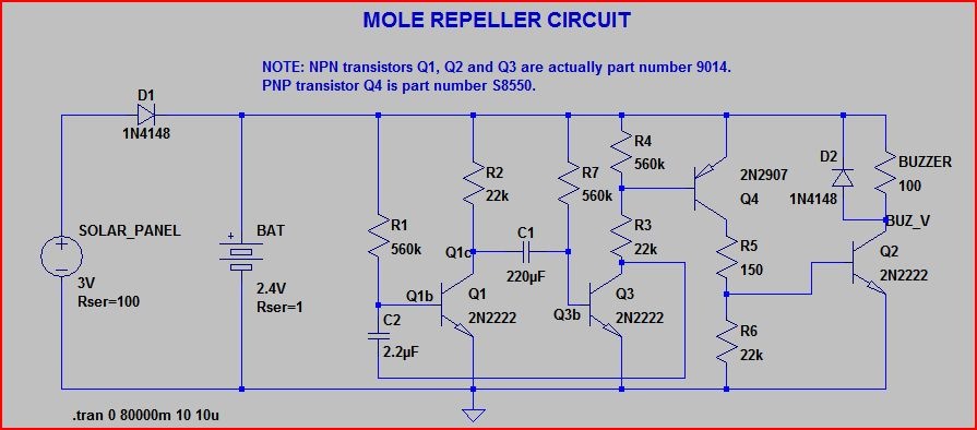
The circuit operates by utilizing a blocking oscillator configuration, where Q1 and Q3 are responsible for generating the on/off pulsing behavior. When Q1 is activated through a resistor (R1), it allows current to flow into the base, turning it on and keeping Q3 off. The capacitor (C1) charges through R7 until it reaches approximately 500 mV, at which point Q3 begins to turn on. As Q3 activates, it also triggers Q4 and Q2, which engages the buzzer. The circuit design ensures that as C2 charges, it eventually turns off Q1, allowing the process to cycle and repeat.
The construction of the buzzer includes a coil that generates an oscillating magnetic field, causing a magnet arm to vibrate against a diaphragm, creating sound. However, the specific components may vary, with assumptions made regarding the transistor and diode used in the circuit. The circuit's inductance values and resistor specifications were estimated, with the resistor confirmed as a 1.5k ohm part. The topology employed is less common, utilizing a control coil connected to ground instead of the supply.
Further analysis indicates that the devices marketed as ultrasonic may operate at frequencies between 300 Hz and 1000 Hz, contrary to their labeling. This frequency range is believed to simulate the sounds of moles burrowing, which may be more effective than ultrasonic frequencies for repelling them. The performance of the product has been subpar, with all units failing due to design flaws, such as inadequate adhesive for the magnet and lack of weatherproofing for the circuitry. These issues have resulted in a lack of reliability for outdoor applications, leading to the conclusion that the design and construction quality of these devices require significant improvement to ensure durability and effectiveness.Having a very healthy population of moles in our vicinity, I logged onto eBay and bought four of the cheaply available (ultra )sonic mole deterrents for our garden lawns in the hope of persuading them to move elsewhere. Here`s a link to a couple of similar ads: eBay ad, eBay ad2. The basic idea is pretty simple and used with other animals too the gadget emits an frequency that the animals in question (in this case the moles) aren`t keen on, so they move away from the area. Some are advertised as being ultrasonic mole deterrent , and some simply say sonic mole deterrent .
Are they sonic or ultrasonic (ultrasonic means above the range of human hearing of which the upper limit is around 20kHz) What frequency do they actually work at Unfortunately the particular model purchased didn`t work for long enough (see below) to answer this question fully, but I`d say they did seem to make a difference initially. Further tests will have to be made on this front. Note that 2N2222 and 2N907 are used in the SPICE circuit as LTSpice doesn`t have models for 9014 or S8550, which are the actual parts used on the PCB.
This matters little to the simulation (see below) as the circuit should work fine with most general purpose bipolar transistors. Q1 and Q3 are responsible for the on/off pulses. If we start with Q1 turned on (via current through R1 into base), Q3 turned off, and either side of C1 at around 0V.
R7 gradually charges up the right side of C1 (Q3b) until the voltage reaches around 500mV at which point Q3 will begin to turn on. When Q3 starts to turn on, Q4 and Q2 (BUZ_V) will also begin to turn on, activating the buzzer. Also the bottom of C2 will be pulled to ground, which will also pull Q1s base (Q1b) low, turning it off this will raise the voltage on the left (Q1c) and right side of C1, accelerating Q3s turn on.
Things will stay like this for around 1 second until C2 charges up through R1 and the base of Q1 (Q1b) reaches ~500mV, at which point Q1 will turn on and C1 will be pulled low, pulling the base of Q3 to ground and turning Q4 and Q2 (and the buzzer) off again. Then the process repeats . If we run the simulation of the above circuit in LTSpice we get these waveforms (waveform names below correspond to bracketed names in the description and labels in the schematic above): So, how accurate is the simulation Pretty accurate as it turns out here are the waveforms for Q1c (yellow) and Q3b (red) over 30 seconds, we can see they are almost identical to the simulation: It`s a very simple construction, consisting of one resistor, a transistor of some sort, a magnet on an arm and a coil with two windings to produce what is called a blocking oscillator .
The electromagnetic coil produces an oscillating magnetic field which makes the magnet arm vibrate against a diaphragm producing the sound. Some guesswork has been applied here as the (unmarked) transistor has 4 pins, not the usual 3. I think there may be a diode (represented by D2, possibly for temperature compensation) included in the package with it`s cathode connected to ground, so pin 4 would be the anode of D2.
The part numbers 1N4148 and BC847C are not the real part numbers, just a random diode and NPN from the LTSpice library. The coil inductance values are guessed at too, but the resistor is definitely a 1. 5k part. This is not the most common blocking oscillator topology, with the control coil from base to ground (via biasing/compensating diode) rather than from supply to base (see below joule thief example) For further reading, Wiki has good pages on the blocking oscillator, and also the popular Joule Thief which utilises such an oscillator: For the version I think is used in our buzzer I managed to track down a buzzer patent 4, 065, 733 which describes the use of a diode subject to the same thermal changes (e.
g. ideally part of the same IC) as a compensating bias element. The links above all have explanations of operation, but here is rough run through. If we begin with Q1 turned on, L_DRIVE_COIL begins to charge. Since it is coupled to L_CONTROL_COIL, the changing current induces a voltage across L_CONTROL_COIL keeping Q1 turned on. As the magnetising current slope levels out on L_DRIVE_COIL, the induced voltage into L_CONTROL_COIL drops.
This lowers the voltage across L_CONTROL_COIL, stealing base current and begins to turn Q1 off. As Q1 turns off, L_DRIVE_COIL attempts to keep the current flowing and a voltage of the opposite polarity appears across it. Since it is coupled with L_CONTROL_COIL this accelerates the turn off process, with a voltage of the opposite polarity appearing across L_CONTROL_COIL bringing the base voltage below 0V.
Q1 remains turned off until L_DRIVE_COIL discharges (i. e. blocked , hence the name) and the voltage on L_CONTROL_COIL drops, allowing the transistor to begin to turn on again. So, it`s not ultrasonic. My suspicion is that they all work around the same frequency (300-1000Hz) but some advertise as ultrasonic, presumably being unaware of the meaning (or maybe as they think it sounds better) Some ads (such as this one ) advertise ultrasonic, but then state an operating frequency of 400-1000Hz in the specs, which seems to support this theory.
The low frequency is apparently meant to simulate the sound of other moles burrowing. This makes more sense to me than an ultrasonic frequency for repelling moles, but I couldn`t find much data on what frequencies work best, or the hearing range of the mole. To put it simply, the quality of this product is pretty terrible. They are not built to withstand continuous operation outdoors. Reasonable proof of this was the fact that out of the 4 purchased, within a few months of use outside, all 4 were no longer working.
So what went wrong Although there is nothing wrong with the principle of the buzzer operation, unfortunately the actual design of the buzzers in this product is not up to scratch. 3 out of the 4 failed due to the permanent magnet on the end of the armature coming loose as can be seen below (note the magnet is separated from the arm and lying on the white sealant stuff): On inspection, it was found that the magnet is simply glued on with what appears to be something like super glue.
This is simply not going to stand repeated vibration for long. Another issue is that the enclosure is not well sealed and none of the circuitry is weatherproofed (e. g. conformal coating or potting) This fact caused the remaining one to fail: 🔗 External reference
Related Circuits
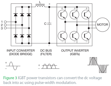
An AC drive controls AC induction motors and, similar to its DC counterparts, regulates speed, torque, and horsepower. A DC drive typically manages a shunt-wound DC motor, which features separate armature and field circuits. This teardown of the Schneider...
The NE568A (NE568AD, NE568AN, SA568AD, SA568AN) is a monolithic phase-locked loop (PLL) that operates from 1Hz to frequencies exceeding 150MHz. It features an extended supply voltage range and a lower temperature coefficient of the VCO center frequency compared to...