
motion detector schematics

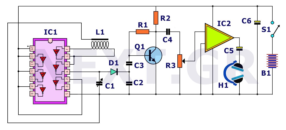
The circuit includes an audio oscillator formed by the IC, resistors R3 and R4, and capacitor C1. The oscillation frequency can be estimated using the formula f = 1.443 / (R3 + 2R4) * C1, typically set around 580 Hz. In its normal state, the phototransistor VT1 does not receive light, resulting in high internal resistance, which keeps the reset pin of the IC low, maintaining the circuit in a non-audible state. When a button on any infrared remote control transmitter is pressed, the infrared pulse signal is detected by VT1, which lowers its internal resistance, allowing VT2 to conduct. This action raises the reset pin of the IC to high, enabling the audio oscillator to output a signal through pin 3, activating the piezoelectric ceramic B and illuminating the LED.
Optional components include the NE555 timer IC, which can also be substituted with FX55A55 or 5G1555 models. The phototransistor VT1 is of the 3DU31 type, while VT2 is a silicon PNP transistor with a gain of 100, such as the 9015. Standard 3mm or 5mm red LEDs may be used for visual indication. The circuit is powered by a 6V laminated battery, which helps reduce the overall size. The piezoelectric component HTD-27A is recommended for sound output.
For assembly and testing, the printed circuit board (PCB) diagram is provided. The phototransistor VT1 must be shielded from light, with a casing thickness between 2mm and 5mm being appropriate. A red filter plastic sheet should be placed over VT1 to prevent ambient light from causing false detections. To enhance sound output, a piezoelectric sound chamber can be constructed. During the debugging process, the resistance of the variable resistor RP should be set to a minimum, and the infrared remote control transmitter should be aligned with VT1. By pressing a button on the remote control, the resistance of RP can be adjusted until an audible detection signal is achieved.To quickly determine the remote control transmitter is good or bad, you can use the remote control detector as shown. If the detected remote control transmitter is good, it will instantly audible alarm signal. The detector can be used to detect various types of color TV, VCR, music center, air conditioning, remote control transmitter quality, ease of use.
Circuit: As shown in the circuit of the detector schematic. By the IC, R3 and R4, C1 form an audio oscillator, the oscillation frequency by the formula f = 1. 443 / (R3 2R4) C1 estimate. The circuit around the audio settings in the 580Hz. Normally, VT1 phototransistor has not been the role of light, its large internal resist ance, making the deadline VT2, and the IC`s reset pin is low and the end of 4 in the main reset state, pin 3 is low, so the circuit does not audible signal. When you press the test of any infrared remote control transmitter of a remote control button, the infrared pulse signal is received VT1, VT1 makes a very small internal resistance, the corresponding conduction VT2, IC 4 feet high, this time in the audio IC oscillation phase, 3 pin output audio signal, so that the piezoelectric ceramic B sound, and LED is lit.
Optional components: IC 555 using a single time base IC NE555, can also be used FX55A55, 5G1555 models. VT1 is 3DU31 type phototransistor. VT2 selected magnification 100 Silicon PNP-type transistor 9015. Use ordinary sound 3mm LED red light-emitting diodes, or LEDs can sound 5mm. G using the laminated battery 6V power supply, to reduce its volume. B Select piezoelectric ceramics HTD-27A. Production and commissioning: The figure is the detector assembly of printed circuit board diagram. Phototransistor VT1`s not exposed by the light part of the case, the order from the case 2mm - 5mm is appropriate, and in the VT1 of the hole set up by the red filter light plastic sheet to prevent ambient light exposure on the VT1, causing false positives.
B, made to improve the sound level should be set up to help piezoelectric sound chamber. Debugging, the first RP to minimum resistance, and then align the infrared receiver remote control transmitter VT1, and press a single button remote control, and then adjust the resistance of RP, it is just the audible detection signal can be. To be cut in the corporate division as an example, Google and other competitors regard the enterprise search service seen as "very important" sector, while Baidu is just the reductions in this sector.
For example, users to search for a pharmaceutical company producing a new drug, the drug would have cost a dollar, if you buy Baidu`s bid ranking "advertisement", you can position in front of the information showed that the cost of the two drugs dollars, he thought it might be misleading to consumers. A friend of anonymity told me: Baidu is facing an unprecedented crisis. His three reasons: Nov. 14 at the Kunlun Hotel in Beijing, "search. Future, "the party, in addition to Baidu and other search engine providers for all participants took part in the discussions, particular emphasis on the fairness of the search engine results, it is
🔗 External reference
Related Circuits
The MSF transmitter transmits time data bit-by-bit over 60 seconds each minute by modulating a 60 kHz carrier frequency. It employs a continuous wave (CW) signal. Two bits are sent every second through variations in the duration and number...
The principle behind a metal detector is quite simple. This is demonstrated by the following circuit, which shows that a metal detector can be constructed quickly with a few readily available components. This metal detector circuit can detect a...
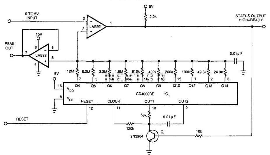
A 0-to-5 V input drives the negative input of the LM392 comparator if the reset (pin 12) of the DC4060BE is pulled high and then low, causing all outputs of ICF1 to be forced low. This action forces the...
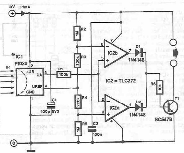
This infrared detector circuit utilizes the PID20 integrated circuit manufactured by Siemens, which converts thermal radiation into electrical impulses. It includes an operational amplifier and several electronic components. The output signal at pin 3 is compared to a reference...
This project has not been called a GOLD detector as this name has been left for the more complex detectors that actually discriminate between gold and other metals. There is an enormous difference between detecting gold and ordinary metals...
A small bias on the bases of Q1 and Q2 through R1 and R2 assists in initiating the circuit. This provides each transistor's base with a slight forward bias, enabling both transistors to conduct when the circuit is initially...