
Motorola VWA63 Auto Radio

The Motorola VWA63 Auto Radio utilizes a superheterodyne architecture, which is a common design for AM radios that enhances the quality of signal reception and selectivity. The circuit typically consists of several key components: an antenna, a radio frequency (RF) amplifier, a mixer, an intermediate frequency (IF) amplifier, a demodulator, and an audio amplifier.
The antenna captures AM radio waves, which are then fed into the RF amplifier. This stage amplifies the weak signals received from the antenna. The amplified RF signal is then mixed with a locally generated frequency from a local oscillator within the mixer stage. This process converts the signal to an intermediate frequency, which is easier to process.
After mixing, the resulting signal is passed to the IF amplifier. This stage further amplifies the intermediate frequency signal while providing improved selectivity and sensitivity. The demodulator then extracts the audio information from the IF signal. This is typically achieved using envelope detection, which recovers the original audio waveform from the modulated carrier wave.
Finally, the audio amplifier amplifies the demodulated signal to a level suitable for driving the speakers in the vehicle. The schematic for the Motorola VWA63 Auto Radio would detail the specific connections and values of components, including resistors, capacitors, and transistors, that make up each of these stages, ensuring optimal performance for AM broadcast reception.Motorola VWA63 Auto Radio is an automotive type all-transistor superheterodyne AM radio for standard broadcast reception. The following schematic illustrates.. 🔗 External reference
Related Circuits
This is a measurement I did on a FM receiver (MC3372). I have plotted the output DC-bias as a function of the IF (Intermediate Frequency) frequency. At 455kHz you can see that I have 5.5V DC bias. When I...
Automated frog call data loggers have been effectively utilized to gather information on: (1) species presence during sampling, enabling the reliable recording of species that may be overlooked due to time constraints; (2) life history and phenology details, such...
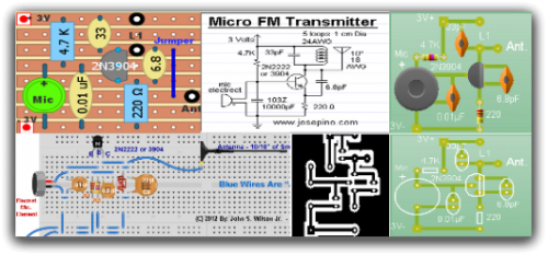
Radio-Circuits has elevated the standard with this website. Unlike any other circuit site on the internet, they have compiled ten of the most popular FM transmitter circuits. Radio-Circuits provides a comprehensive collection of FM transmitter circuits, showcasing a variety of...
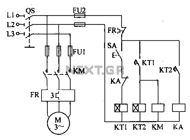
After the power switch is activated, the motor does not start immediately but instead has a specified delay period. This setup allows the machine to perform automatic intermittent lubrication control. The circuit for the motor boot delay and intermittent...
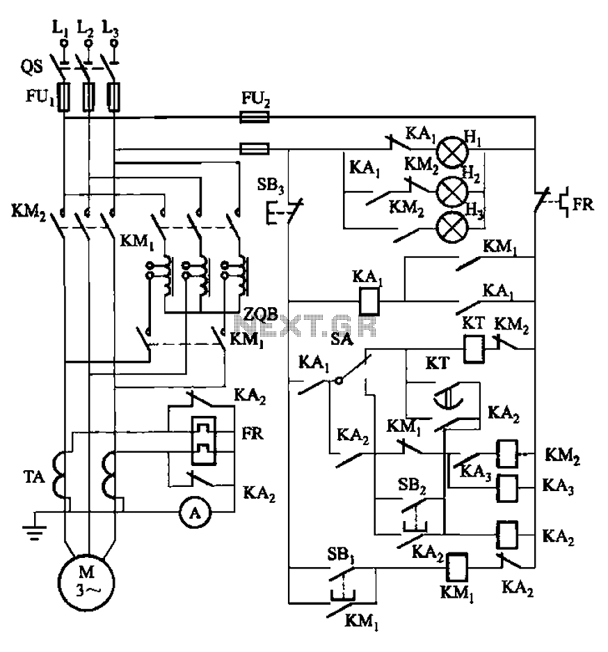
The circuit illustrated in Figure 3-56 features both manual and automatic start-up modes. It incorporates two relays, KA2 and KA3, within the control loop. The circuit design ensures that KM1 is cut off before and after activating KM2. A...
This simple and cost-effective device is designed to automatically feed fish, alleviating concerns about their starvation. The autofeeder dispenses pellets based on user-defined quantities and time intervals. Constructing this circuit is an engaging activity that fosters creativity. The primary...