
new laser warning sticker
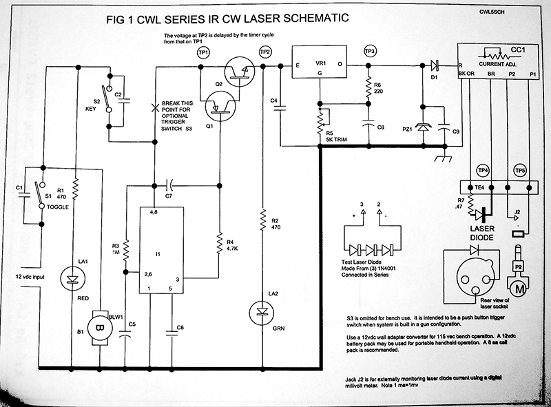
The circuit described involves a laser system where a potentiometer is used to control the power output. The shorting wire connected to a resistor may have been intended to modify the behavior of the circuit, particularly affecting the operational amplifier that manages the current supplied to the laser diode. The operational amplifier's role is critical, as it ensures a stable current flow and mitigates potential damage from voltage spikes that can occur when the laser is powered on or off.
In this setup, the potentiometer should allow for fine-tuning of the laser's output, but the introduction of a shorting wire may have inadvertently altered the expected functionality, leading to a cycle of brightness changes upon startup. This behavior indicates that the feedback loop, typically provided by the operational amplifier, may have been compromised, resulting in uncontrolled current flow to the diode.
Additionally, the presence of Loctite on the threads suggests that the laser head is designed to remain securely fastened, minimizing the risk of misalignment or operational failure. The discussion of using SPICE for circuit simulation highlights the importance of pre-testing modifications in a virtual environment to prevent physical damage to the components.
In summary, the circuit's design emphasizes the need for careful handling of the potentiometer and associated components to maintain the integrity and functionality of the laser system. The operational amplifier's protective role cannot be overstated, as it serves to ensure the longevity and reliability of the laser diode in operation.Did you take that shorting wire off the resistor What about your pot, did you leave it cranked on full power What kind of increase do you think turning the pot gave you Good I suppose. I haven`t yet disconnected the shorting wire, but at the same time I haven`t used the laser much either.
i`ve been busy trying to draw up a schematic of the board. Once I get it done, I want to plug it into SPICE, that circuit simulator program. does anyone here have experience with that I figure with that program I could safely poke around without fear of frying the thing. The pot is still cranked at full power. When I was shining the thing on the wall without the heat fins/lense, (so I had one gigantic dot) the dot got maybe 10-15% brighter.
but I have no idea how that translates to actual brightness once the thing is focused back down to a beam again. the tiny dot went from "hurts to look at" to "really really hurts to look at" Since shorting the resistor, does it still go through that cycle of brightness changes when 1st powered on Did you notice this at all with the just the pot adjustment One more question, after removing the heatsink end and viewing the laser head directly, I see what looks like a few drop of loctite thread lock on the threads holding the laserhead to the body, did yours have these drops as well What I would do is trim off the white border around the triangle and the warning test, that way it would just be yellow and would look much more cool.
I think. I used this Matte glossy cd label paper. but i just cut out the square shape from the label. My printer is a cannon pixma ip3000 that I got off slickdeals. net for 20 dollars. which is funny because replacement ink is more expensive than I paid for the printer. Bad news on the laser front. last night I tried to disconnect my shorting wire, and somehow fried the laser driver board. (I think it`s this stupid "cold heat" soldiering iron I have. as I was soldiering the damn LED came on, WTF. Anyways, I came up with a workaround to get the laser working, but in general i`m thinking about re-building the entire board. Since shorting the resistor, does it still go through that cycle of brightness changes when 1st powered on Did you notice this at all with the just the pot adjustment One more question, after removing the heatsink end and viewing the laser head directly, I see what looks like a few drop of loctite thread lock on the threads holding the laserhead to the body, did yours have these drops as well What is loctite Is it like glue I didn`t see any of that, (or if there was some, it broke immediately as I unscrewed my aluminum ring.
) That brightness cycle at boot only started when I shorted the resistor, I didn`t notice any of it when I shorted the pot. After some investigation, I think the resistor I shorted was going into that dual operational amplifier chip.
Are the PGL-III`s supposed to have an optical feedback circuit If so i`m imaginging that`s what the dual op amp was being used for. so shorting that resistor just disabled it. It`s like a glue that is used to lock the threads so that it does not become unscrewed/loose. I thought you just turned the pot, not shorted it. The PGL-III does not have optical feedback. The op-amps are used to provide a constant current and prevent current or voltage spikes when the laser is turned on or off.
Without it the sudden inrush of current when the device is turned on will soon destroy the diode as it is very sensitive to these spikes that happen when the power switch is opened or closed. It also works to protect against static electricity when the device is on as well. What`s your electronics background Se 🔗 External reference
Related Circuits
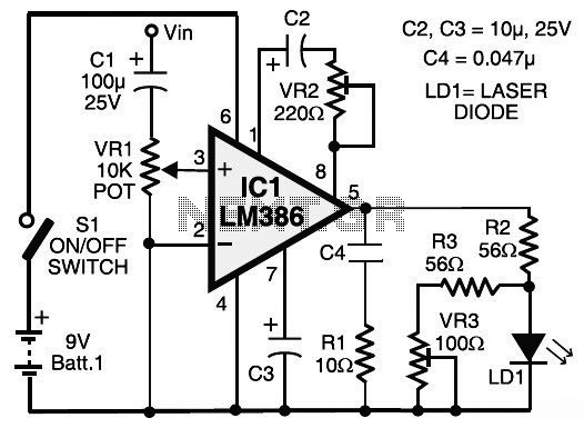
This circuit diagram represents a laser communication system that transmits sound or music signals using a laser beam. The intensity of the laser beam varies in accordance with the amplitude of the sound signal. The variation in the intensity...
The power supply has been simplified. Power transformers and rectifiers have been omitted, and some components have been removed from the MOSFET voltage regulator circuits: 1N5242 zener diodes between the source and gate and 10k resistors in series with...

An interferometer is primarily utilized for calculating the index of refraction of gases and transparent materials, such as air and glass. This process involves counting each interference circle individually. Achieving precise measurements necessitates counting up to a hundred circles,...
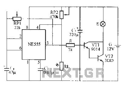
This circuit utilizes battery-powered blinking warning lights for roadblocks. It can operate on AC power to create barricades with warning indicators. The circuit incorporates an NE555 timer and resistors RP1 and RP2, along with resistor R1, to form a...
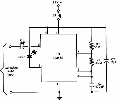
Due to the high frequency of light within the electromagnetic spectrum, it serves as a superior medium for communication compared to radio waves. Lasers are ideal for communication links because they produce a powerful and narrow beam that is...
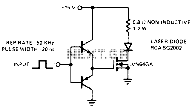
This drive is capable of supplying the laser diode with 10 ampere pulses lasting 20 ns. With a 0% duty cycle, the repetition rate is 50 kHz. A complementary emitter-follower configuration is utilized as a driver. Switching speed is...