
Nicad/NiMH Charger
Hit the button to display the cell count again. -or- Hold the button until you see one flash of the red light. -then- Hit the button to enter the program mode - one flash of the red light. -then- Hit the button once for each cell - light flashes for each hit. -then- Hold the button to store count and return to start -or- Hold the button until the red light comes on steady - unit will start charging. -then- Wait for charge to end. -or- Hold down to return to start.
During charging the red light 'winks' out about once per second for each volt short of a full charge. The result is that it flashes faster as full charge is approached. A timeout is provided if full charge is not achieved after several hours.
Once full charge is complete. The red light repeatedly flashes once and a small charge current (short pulse) is applied to the batteries. Two flashes indicates that the unit timed out.
The device utilizes a Microchip PIC12F675 microcontroller, which is responsible for managing the operation of the battery charging system and the user interface through a single button. The power supply range of 12 to 24 volts DC is suitable for various battery configurations, specifically accommodating between 1 to 8 cells.
The operational logic begins upon power application, indicated by the illumination of a green LED, which signifies that the device is powered and ready for interaction. The red LED serves a dual purpose: it provides feedback on the number of cells programmed and indicates the charging status.
The user interacts with the device through two distinct button actions: a short press (Hit) and a long press (Hold). The Hit action allows the user to quickly check the current cell count, while the Hold action initiates a programming mode. In this mode, the user can increment the cell count by pressing the button, with each press resulting in a corresponding flash of the red LED. To save the programmed cell count, the user must hold the button again, which stores the value in the microcontroller's EEPROM, ensuring that the configuration is retained across power cycles.
When the device is switched to charging mode, the red LED provides visual feedback on the charging progress. It flashes at a rate proportional to the voltage deficit from a full charge, allowing users to monitor the charging status intuitively. If the charging process surpasses a predetermined timeout period without reaching full charge, the system will indicate this failure through a specific LED flash pattern.
Upon successful completion of the charging cycle, the red LED emits a consistent flash pattern, signaling that a small pulse of current is being delivered to the batteries, which helps maintain their charge. The device is designed to be user-friendly, with a clear feedback mechanism through LED indicators and a streamlined button interface that simplifies operation while ensuring effective battery management.This device is built around a PIC12F675 (a dandy little part from Microchip). The number of cells (1 to 8) is programmed in using the one button. The cell count is saved in EEPROM the next time you power up the device. Using just one button for all operations is a bit tricky, but easy once you try it a few times. There are 2 types of button operations: Hit (less than 1 second), and Hold (over 1 second). Here is what to do. Apply power (12 to 24 volts DC) to the jack. Then, connect the batteries. The green light comes on (indicating power applied) The red light flashes once for each cell. -start- Hit the button to display the cell count again. -or- Hold the button until you see one flash of the red light. -then- Hit the button to enter the program mode - one flash of the red light. -then- Hit the button once for each cell - light flashes for each hit. -then- Hold the button to store count and return to start -or- Hold the button until the red light comes on steady - unit will start charging. -then- Wait for charge to end. -or- Hold down to return to start. During charging the red light 'winks' out about once per second for each volt short of a full charge.
The result is that it flashes faster as full charge is approached. A timeout is provided if full charge is not acheived after several hours. Once full charge is complete. The red light repeatedly flashes once and a small charge current (short pulse) is applied to the batteries. Two flashes indicates that the unit timed out. 🔗 External reference
Related Circuits
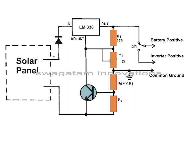
Solar panels are well-known devices that convert solar energy or sunlight into electricity. A solar panel consists of discrete sections of individual photovoltaic cells, each capable of generating a small amount of electrical power, typically between 1.5 to 3...
Although not a new device, the LM317 is still a high-performance regulator. Its output voltage is essentially immune to fluctuations in load and supply voltage. The LM317 is a versatile adjustable linear voltage regulator widely used in various electronic applications....
This project is one for the experimenter, but as shown will work extremely well. The sensing circuit can be made so sensitive that a load of only 2.5mA is enough for the circuit to detect, and disconnect the charger....
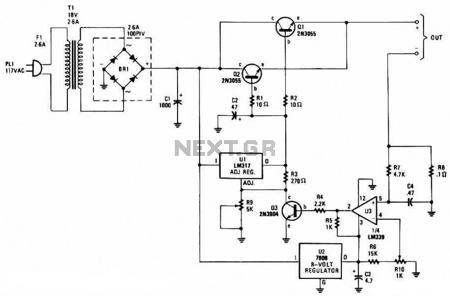
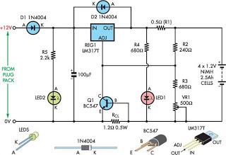
This battery charger circuit is regulated and adjustable, enabling it to charge most NiCAD batteries. It is suitable for single cells or multiple battery cells connected in series or parallel configurations. The maximum... This battery charger circuit is designed to...
As the circuit operates, the three sets of diodes with their isolation capacitors build up an increasing voltage on capacitor C1. The voltage at point B will also increase and be about twelve volts less than the voltage on...
This is a low-cost universal battery charger circuit. This circuit is designed to charge NiCd and NiMH batteries and is ideal for use in vehicles. The circuit converts mains voltage. The low-cost universal battery charger circuit is engineered to efficiently...