
Nixie Clock 2
The clock circuit operates on a dual-board system, enhancing both functionality and compactness. The high-tension generator and the processor logic are strategically placed on one board, while the tubes are situated on a separate board. This layout not only aids in space management but also allows for better thermal dissipation and easier troubleshooting. The use of a 0.3" DIP grid for tube placement, although not optimal, ensures that the tube legs are adequately supported through diagonal bracing. This design consideration mitigates the risk of mechanical stress on the tube leads, which is crucial for maintaining the integrity of the seals and overall performance of the nixie tubes.
The enclosure, crafted from recycled ebony, adds an aesthetic value while also being environmentally conscious. The process of cutting, gluing, sanding, and polishing the ebony sheets showcases a commitment to quality craftsmanship. The decision to drill holes prior to assembly demonstrates foresight in design, although the slight misalignment due to pre-bent legs of the nixie tubes highlights the challenges of using recycled components.
In terms of power supply, the choice of a surplus laptop power supply is both practical and efficient, providing a regulated 15V output capable of handling the necessary current for the nixie tubes and the driver logic. The estimated current consumption of 1mA per tube at 180V indicates a well-calibrated design that balances performance with energy efficiency. The time-setting mechanism, utilizing two switches for user interaction, is intuitive and enhances the overall user experience.
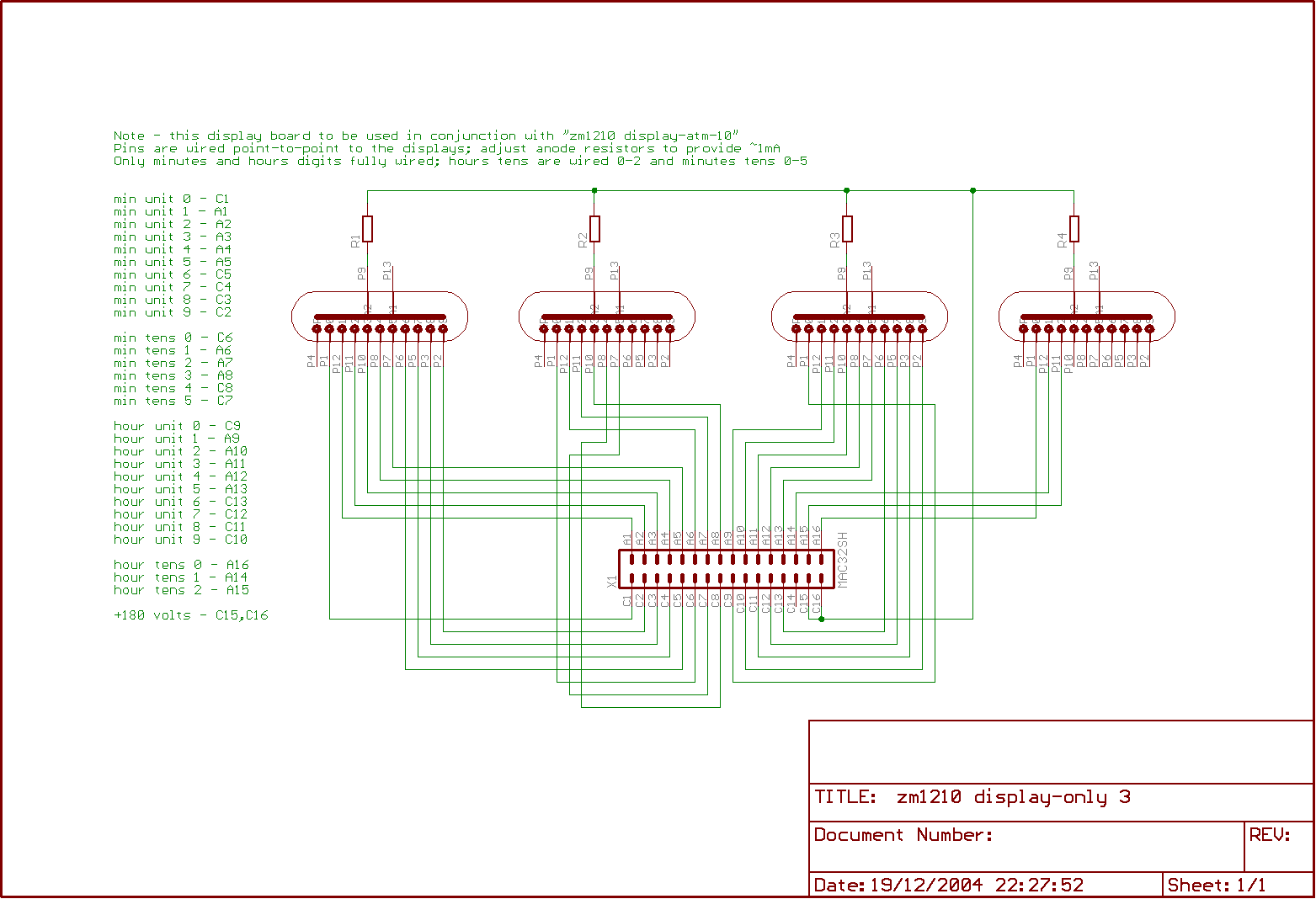
Safety precautions are paramount, given the presence of high voltage on the circuit boards. The warning regarding the potential for electric shock is critical, emphasizing the importance of proper handling and the need for adequate safety measures when working with high-voltage electronics. This detailed design not only serves as a timekeeping device but also as a testament to innovative engineering and the importance of safety in electronics.The clock is constructed on two boards; one carries the HT generator and the processor logic, the other the tubes. Thisallows a slightly more compact design that the previous effort, but didn`t save as much real estate as I`d hoped.
The tubes are mounted on a DIP 0. 3" grid. This isn`t ideal, but it has the advantage that the tube legs are diagonally braced and are far enough separated that tracks can be run between the lands. The bad news is that if the tubes are placed nearer than half an inch or so to the board, there is excessive stress on the leads which might have adverse effects on the seal. The box is cut from recycled ebony. 3mm thick sheets were cut from a block and glued together to create the shape; it was sanded on a belt and then by hand for the smooth surface, which was then polished using Danish oil and elbow grease.
The holes were drilled before glueing but after cutting. The reason they`re a little off-centre isn`t a problem with the circuit board; I used recycled nixies too and the legs were a little bent before I soldered them in, and the holes are cut to fit. There are no particular efforts taken to regulate the crystal, but in service in the case, it`s been gaining a second a week.
Near enough for me, I think; it`s usually closer to the real time than another mains-regulated nixie clock I also have. I don`t like mains on circuit boards, particularly when - as here - there might be a risk of exposed mains in the case of a breakage, and there wasn`t room for an isolating transformer, so instead the clock is powered through a surplus laptop power supply, providing a regulated 15v at up to 2A.
I haven`t measured the current, but as an estimate - 1mA each at 180v for the tubes; say 50% conversion efficiency gives about 1. 5W for the display, and maybe 200mW for the driver logic. The time is set using the two switches which share the programming connector. One switch cycles between a normal display, a display where only the hours are visible, and one when only the minutes are visible.
The other advances the selected time one hour or minute forward per click. You`ll see that the circuit board for the display has the tracks uppermost. It`s impossible to solder the connector on a single sided board otherwise. Both boards are single sided, though the controller board has half a dozen wire links which I`ve shown on the layouts as top-side tracks. Be warned; there are 180v on the exposed tracks on the upper circuit board, and also at sundry points along the back of the control board.
It`s not referenced to earth, but there`s still enough volts there to give you a jolt and enough current for a potentially dangerous or fatal shock. If you don`t know what you`re doing around high voltages, don`t build or operate this circuit. 🔗 External reference
Related Circuits
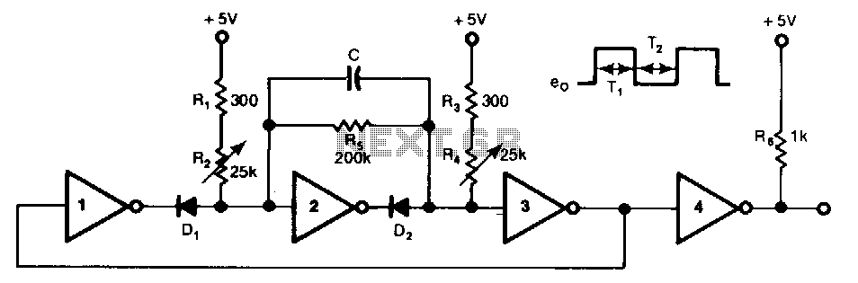
This free-running TTL square-wave oscillator features a variable frequency output spanning a 20:1 range or better. It utilizes four of the six inverters in an SN7404 chip along with additional components. The frequency of oscillation is dictated by the...
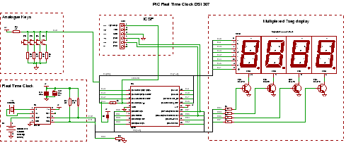
PIC RTC: A Real Time Clock IC using the DS1307 and a PIC microcontroller. This PIC project utilizes an I2C Real Time Clock chip and a display to create a four-digit standard desk clock. The described project incorporates a DS1307...
This is the timekeeping test circuit. It includes a one-transistor circuit to switch in the 5V power supply when present and drop back to the 3V battery the rest of the time. That loop of blue wire-wrapping wire is...
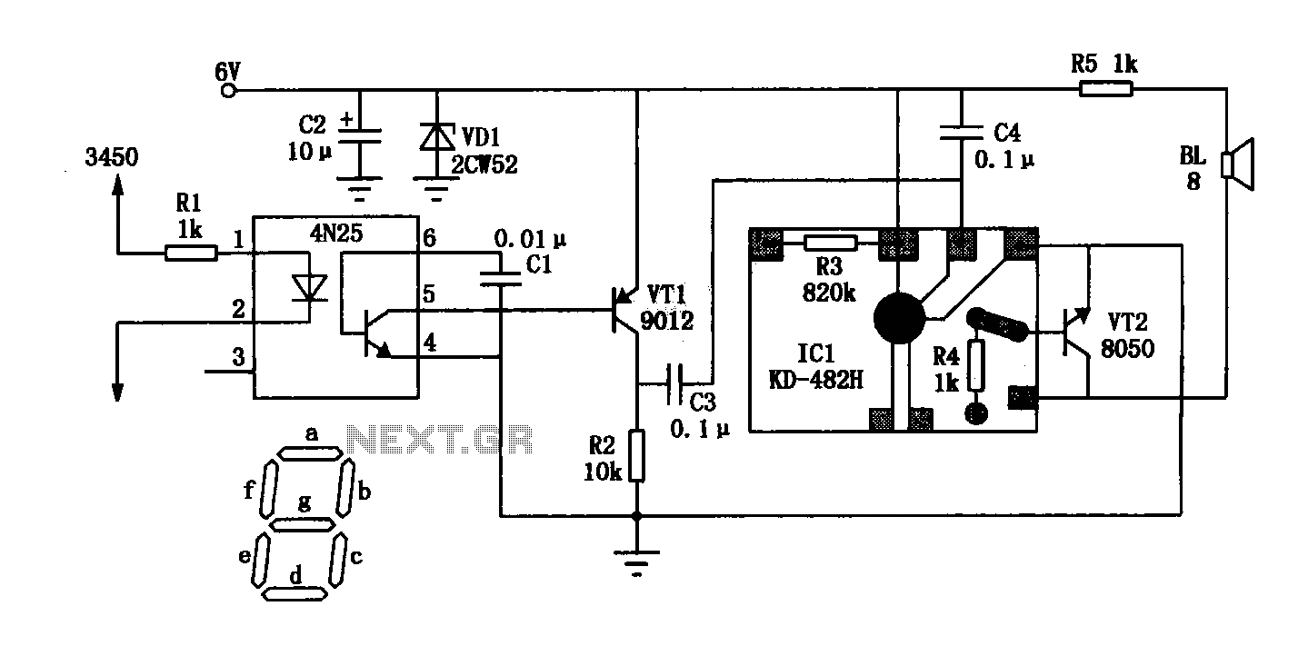
The General Dynamic LED digital clock lacks a timekeeping function, but by adding a simple circuit, it can incorporate this feature. The integrated circuit (IC) includes a programmable mute function, which is inactive from 23:00 to 5:00 to avoid...
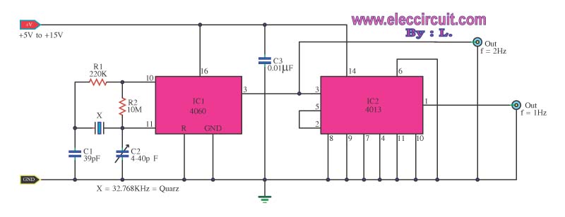
This is a standard digital clock circuit with a frequency of either 1 Hz or 2 Hz. It can be utilized in a conventional clock circuit. The circuit comprises IC-4060 and IC-4013. The digital clock circuit operates by utilizing the...
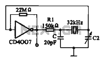
A 32 kHz clock oscillator is essential for digital circuits, as depicted in the schematic. The 32 kHz crystal clock oscillator serves to provide a time reference signal for the digital circuit. It utilizes a CMOS integrated circuit, specifically...