
NMEA to RS232 Interface Board

ICs:
- MAX232CPE RS232/TTL Interface
- CD4049UBE Hex Inverting Buffer
- L7805C 5 Volt Regulator
Capacitors:
- C1, C2, C3, C4, C5: 22 microfarad (electrolytic - 16 volt working)
- C6: 10 microfarad (electrolytic - 16 volt working)
- C7: 100 microfarad (electrolytic - 16 volt working for 12 volts in, electrolytic - 50 volt working for 40 volts in)
Resistors:
- R1, R2: 4.7K ohm (4700 ohm)
Diode:
- D1: 1N4002 Power Diode
Two Postscript files are included, which can be printed directly or utilized as EPS files without further scaling.
The circuit design, based on Andrew Bruno's original concept, serves as a voltage level shifter for integrating early GPS units with RS232 interfaces. It addresses the limitation of early GPS devices that output TTL levels without negative voltage, making them unsuitable for direct connection to certain RS232 interfaces. The MAX232CPE integrated circuit is pivotal in this design, as it facilitates the conversion of TTL levels to RS232 levels, ensuring compatibility with a broader range of devices.
The inclusion of the CD4049UBE hex inverting buffer serves to stabilize the signal and improve the integrity of the communication between the GPS unit and the RS232 interface. The L7805C voltage regulator is responsible for providing a stable 5V power supply to the circuit, ensuring consistent operation.
The capacitor selection is critical for filtering and stabilizing voltage levels throughout the circuit. The electrolytic capacitors (C1-C5) provide decoupling, while C6 and C7 are specifically chosen to handle voltage fluctuations from the power supply, with C7 rated for higher voltage operation to accommodate varying input conditions.
The resistors R1 and R2 are utilized for biasing and limiting current within the circuit, ensuring that the components operate within their specified parameters. The 1N4002 diode serves as a protection mechanism against reverse polarity, safeguarding the circuit from potential damage.
Overall, this circuit design is a historical reference point for interfacing early GPS technology with RS232 communication standards, though it is advised against using it with newer NMEA-0183 compliant systems due to differences in output requirements. The provided Postscript files facilitate the reproduction of the PCB layout, ensuring accurate implementation of the design.This design is based on that of Andrew Bruno. His design appeared under the name of "bruno-if". My contribution was to provide Postscript files for a Printed Circuit Board. This circuit is quite old and goes back to the days of NMEA-0180 and 0182. Note that it is non-inverting. Its purpose was to shift the NEMA voltage levels to be RS232 compliant . Many early GPS units were not fully RS232 compliant, in the sense that they did not produce a negative voltage level. The voltages were at TTL levels, but in the same sense as RS232: Although not fully compliant, this meant that a GPS unit could be directly connected to many computer RS232 interfaces, but not to those that required the negative voltage.
NMEA-0183 recommends that a talker output should have EIA-422 differential outputs and that the input circuit should use an opto-isolator with suitable protection circuitry. I cannot, therefore, recommend the use of this circuit with NMEA-0183 compliant equipment. ICs: MAX232CPE RS232/TTL Interface CD4049UBE Hex Inverting Buffer L7805C 5 Volt regulator Capacitors: C1, C2, C3, C4, C5 22 microfarad (electrolytic - 16 volt working) C6 10 microfarad (electrolytic - 16 volt working) C7 100 microfarad (electrolytic - 16 volt working for 12 volts in) (electrolytic - 50 volt working for 40 volts in) Resistors: R1, R2 4K7 ohm (4700 ohm) Diode: D1 1N4002 Power Diode Two Postscript files are provided.
They can be printed directly or used as EPS files. When used as EPS files, they should not be subject to any further scaling. 🔗 External reference
Related Circuits
The LM4550 is an audio codec designed for PC systems, fully compliant with PC99 standards, and performs the analog-intensive functions of the AC97 Rev2.1 architecture. It utilizes 18-bit Sigma-Delta analog-to-digital (A/D) and digital-to-analog (D/A) converters, providing a dynamic range...
The project we have chosen as our example is an RS232 to RS485 converter. This is a often needed device which can demonstrate a lot of principles of circuit design, and hopefully the finished project will be useful to...
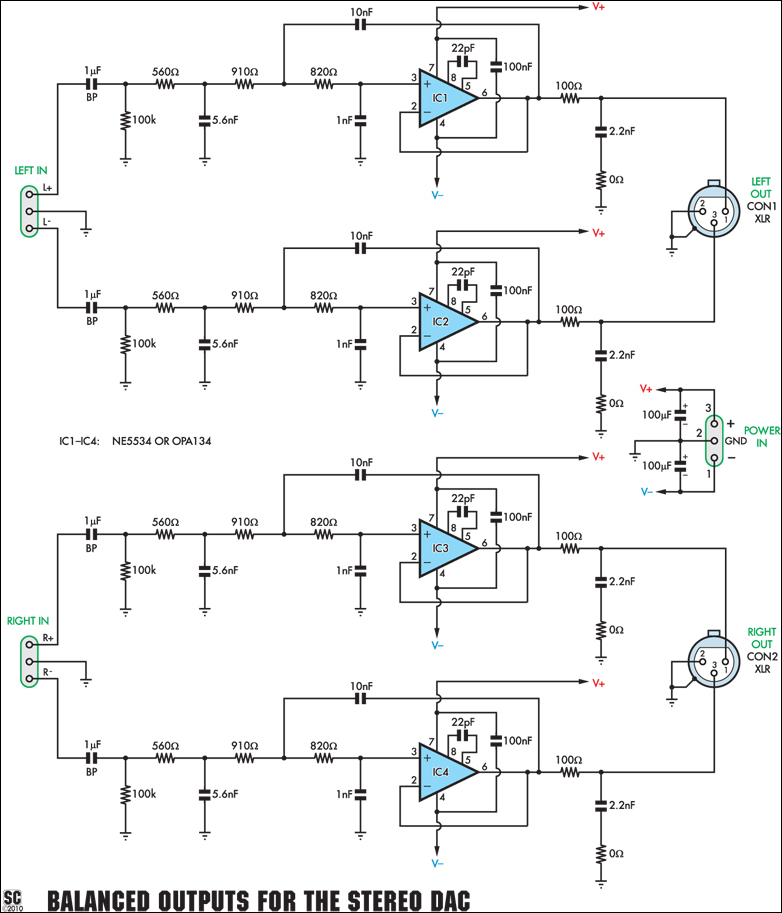
This add-on board is designed to provide a pair of balanced audio outputs for the High-Quality Stereo DAC (Digital to Analog Converter). Two 3-pin male XLR connectors are used for the new outputs, which can either replace or augment...
Ensure to verify all connections utilizing the circuit diagram and breadboard schematic available for download from the provided links. This resource can assist during the assembly process. To create a reliable electronic circuit, it is essential to meticulously verify all...
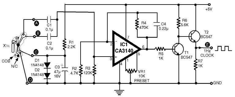
1Hz Clock Generator Circuit with Chip On Board (COB). The COBs used in different watches may differ somewhat in their configuration. However, through trial and error, one can identify the appropriate points corresponding to points A, B, C, and...
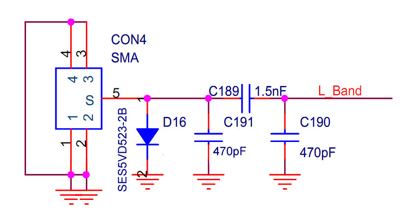
The implementation occurred in the higher frequency L-band (1452-1492 MHz), while the EU, AU, and GB operate in the VHF Band III (174-230 MHz). Unfortunately, it did not succeed for various reasons. The application works well locally, but only...