
Off-line flyback regulator

The circuit is designed to provide efficient power management by utilizing a feedback mechanism that ensures stable output voltage despite variations in load conditions. The UC1842 error amplifier plays a crucial role in this process, receiving the voltage from the primary-side control winding and adjusting the output accordingly. The effectiveness of this feedback system is largely determined by the magnetic coupling between the secondary and control windings of the transformer, which can introduce variations in the output voltage due to leakage inductance.
In scenarios where enhanced load regulation is critical, the UC1901 Isolated Feedback Generator serves as an alternative solution. This device directly senses the output voltage, allowing for more accurate feedback and improved performance under varying load conditions. By integrating the UC1901 into the circuit, designers can achieve tighter control over the output voltage, leading to better overall system stability and efficiency.
The circuit layout should include proper placement of the UC1842 and UC1901, ensuring minimal interference from external noise sources. Additionally, attention must be paid to the design of the transformer, particularly its winding configuration, to optimize the coupling between the primary and secondary windings. Implementing adequate filtering and decoupling techniques will further enhance the performance and reliability of the circuit, making it suitable for a range of applications requiring precise voltage regulation.This circuit uses a low-cost feedback scheme in which the dc voltage developed from the primary-side control winding is sensed by the UC1842 error amplifier. Load regulation is therefore dependent on the jcoupling between secondary and control windings, and on transformer leakage inductance.
For applications requiring better load regulation, a UC1901 Isolated Feedback Generator can be used to directly sense the output voltage.
Related Circuits
When the panel isn't generating, the entire circuit is off and there is absolutely no current drain from the battery. When the sun gets up and panel starts producing at least 10 Volt, the LED lights and the two...
Before designing an adjustable voltage regulator into a circuit or performing a redesign, it is essential to calculate the values for two resistors. While this calculation is straightforward, locating the appropriate resistors may present challenges. Fortunately, a technique exists...
This device is designed to maintain a deep cycle battery using energy harvested from a solar panel. It functions as a combination of a digital clock timer and a solar panel charge controller. Component: .. This circuit serves the dual...
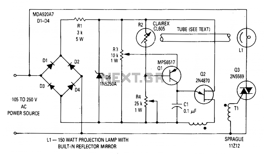
The circuit regulates the RMS output voltage across a load, specifically a projection lamp, to 100 volts ±2% for input voltages ranging from 105 to 250 volts AC. This regulation is achieved by indirectly sensing the light output of...
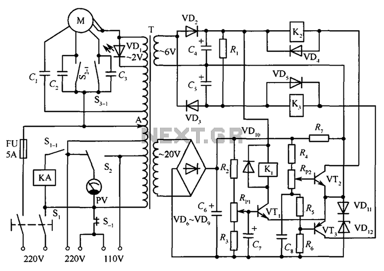
The circuit illustrated in the figure features an automatic voltage regulator (T) that utilizes a servo motor to ensure a constant output voltage. The transistors used are VT1 and VT2 (3DK9C, with a range of 65 to 85) and...
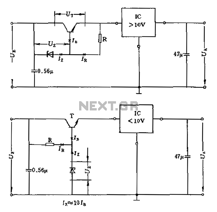
The voltage equation Ue = Ut + Ur + Ua indicates that the transistor voltage Ut will determine the maximum output voltage Ua. Additionally, Ur must be 2V. The voltage regulator's voltage value depends on the selection of Uz....