
One group of integrated circuits using electrical circuit 555 when the load limit

The 555 limit circuit is a practical application of the 555 timer IC in a load management scenario. This circuit can be particularly useful in preventing damage to electrical appliances or systems by limiting the current flow based on specific load conditions.
In its operational state, the circuit continuously monitors the load current. When the load current exceeds the set point, the circuit activates a relay or a switch to disconnect the power supply. This action protects the connected equipment from overheating or damage due to excessive current. The relay can be chosen based on the load requirements and should be rated appropriately to handle the maximum load current.
The configuration of the 555 timer in monostable mode allows for a single output pulse when triggered. The duration of this pulse is determined by the resistor R4 and capacitor C4 values, which define the time it takes for the circuit to reset and allow power to flow again after the load has dropped below the set threshold. The adjustment potentiometer RP provides flexibility in tuning this time delay, enabling the user to set it according to specific application needs.
When designing this circuit, careful consideration should be given to the selection of components, including the 555 timer, resistors, capacitors, and the relay. The circuit should be tested under various load conditions to ensure reliable operation and to fine-tune the delay settings for optimal performance. Additionally, proper heat dissipation measures should be implemented to maintain the integrity of the components during operation.
Overall, the 555 limit circuit serves as an effective solution for load management, enhancing the safety and longevity of electrical systems.555 limit when one group integrated electrical circuit load circuit is shown. It can limit the large load electric power. When the electricity load exceeds a set value, automat ically breaking power; when the load to be reduced to below the set value, it can automatically restore power. It uses capacitor step-down, using 555 IC A composition monostable delay circuit. Adjust R4, C4, can be changed variable delay time adjustment potentiometer RP, you can change the operation setting value.
Related Circuits
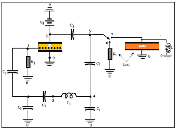
COMSOL's integration of SPICE® elements into its finite element method (FEM) allows for direct modeling of oscillators. In this approach, the triode and load are described using FEM, while all other circuit components are simulated with SPICE®. This modeling...
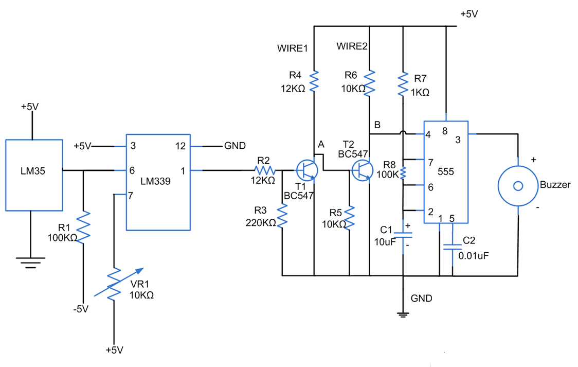
Fires can occur for several reasons, such as forgetting to turn off equipment like irons. A fire alarm circuit with a temperature sensor may be one option to secure homes from fire hazards. There are also fire alarm circuits...
The RF oscillator utilizes inverter N2 and a 10.7 MHz ceramic filter to drive the parallel combination of inverters N4 to N6 through inverter N3. Since these inverters are connected in parallel, the output impedance is low, allowing direct...
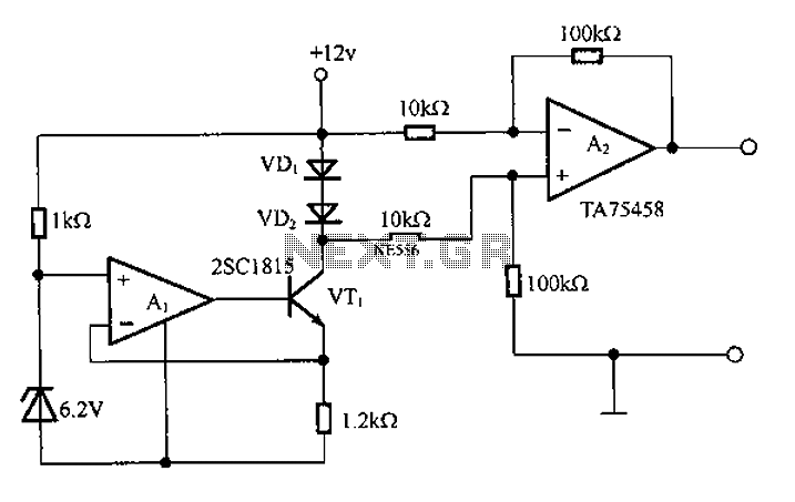
A diode is utilized in a temperature sensor application circuit. Silicon diodes VD1 and VD2 serve as the temperature sensors, exhibiting a temperature coefficient of silicon diodes. The circuit includes a constant current source, VT1, which provides a steady...

A 30- to 50-cm whip antenna provides reception from 10 kHz to over 220 MHz. Tl, a dual-gate MOSFET, provides low noise, high-input impedance, and high gain. The circuit is powered via the coaxial cable used to connect the...
Typically, the base of a cordless phone is equipped with an adaptor, while the handset operates using Ni-Cd cells. In the event of a power failure, the base unit becomes inoperative. To address this issue, it is advisable to...