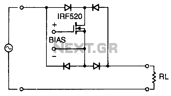
One-mospower-fet-analog-switch

Utilizing four diodes in an array enables the use of a single MOSPOWER transistor for analog switching. The current flow is managed by maintaining the source-base connection of the MOSFET towards the load. It is essential to select diodes that can handle the load current and a transistor with a breakdown voltage rating that exceeds the maximum anticipated analog voltage. Additionally, by increasing the gate-to-source bias voltage, the MOSFET is activated. In applications that require operation between fully on and fully off, it is crucial to avoid exceeding the power dissipation limits of the MOSPOWER transistor. An appropriate heatsink is necessary to prevent overheating in such scenarios.
The circuit design incorporates an array of four diodes arranged in a configuration that allows for effective current steering while minimizing the number of active components required. This arrangement is particularly advantageous in applications requiring analog switching, as it simplifies control circuitry and reduces the overall footprint of the design. The diodes must be selected based on their forward current rating, ensuring they can adequately handle the load current without experiencing thermal runaway or failure.
The MOSPOWER transistor serves as the primary switching element, and its gate-to-source voltage (Vgs) plays a critical role in its operation. When Vgs exceeds the threshold voltage (Vth), the transistor transitions from the off-state to the on-state, allowing current to flow from the drain to the source. Careful consideration must be given to the gate drive circuitry to ensure that the MOSFET is driven into saturation during the on-state to minimize power losses.
In applications where the MOSFET operates in a linear region (partially on), it is vital to monitor the power dissipation. The power dissipation (Pd) can be calculated using the formula Pd = Iload * Vds, where Iload is the load current and Vds is the drain-source voltage. Exceeding the maximum power dissipation ratings can lead to thermal failure, thus necessitating the use of a suitable heatsink to dissipate excess heat generated during operation. The thermal resistance of the heatsink should be selected based on the anticipated power dissipation and the ambient temperature conditions to maintain the junction temperature within safe limits.
In summary, this circuit design efficiently utilizes an array of diodes and a MOSPOWER transistor for analog switching applications, with careful attention to component selection and thermal management to ensure reliable operation.Using four diode in an array allows using only one MOSPOWER transistor for analog switching. The current flow is controlled by keeping the source-base connection of the MOSFET towards the load. Be sure to use diodes capable of handling the load current and a transistor whose breakdown voltage specification exceeds the peak analog voltage anticipated.
Operationally, by increasing the gate-to-source bias voltage, the MOSFET turns on. For applications other than either full-on or fulloff, care must be taken not to exceed the dissipation of the MOSPOWER transistor. A suitable heatsink cannot be overstressed in such applications.