
One power supply circuit soft start

The soft start circuit is designed to limit the inrush current during the initial power-up phase of a load, which can be crucial for sensitive electronic components that may be damaged by sudden voltage spikes. The gradual ramp-up of the output voltage reduces stress on both the power supply and the connected load.
In the circuit, the capacitor Cz plays a vital role in controlling the charging time, which in turn influences the rate at which the output voltage rises. The transistors, specifically VT2, are used to regulate the flow of current based on the voltage across Cz. The diode VD ensures that the current only flows in one direction, preventing potential damage to the circuit during the discharge phase of Cz.
Resistor R6 can be used to fine-tune the discharge rate of the capacitor, while capacitor C2 can be adjusted to modify the time constant of the circuit, allowing for flexibility in the soft start duration. By selecting appropriate values for R6 and C2, the designer can achieve the desired soft start characteristics, ensuring that the load is powered up smoothly and without abrupt changes in voltage.
Overall, this soft start circuit is essential for applications where load protection is critical, providing a reliable method to manage power delivery during startup.The so-called soft start, refers to a circuit power, the output voltage through a startup process to a slower rate of increase to a given value, in order to protect not want to have surges of the load circuit. It can output voltage 24V, current 2A. Soft-start circuit by the capacitor cz, transistors VT2 and diode VD composition. Adjust R6 and C2, available when needed playing time levy.
Related Circuits
This application note explains how the transfer function of most operational amplifier circuits can be derived through a straightforward process of nodal analysis. The transfer function of operational amplifier (op amp) circuits is a critical aspect for understanding their behavior...
A radio camera on a model railway is designed to transmit continuously while the train is in motion and to continue transmitting for a few minutes after the train stops. If the train starts moving again after a relatively...
This circuit indicates the power level delivered to a loudspeaker. A dual-color LED displays green at approximately 1 watt, orange at 1.5 watts, and bright red at levels exceeding 3 watts. The circuit is connected in parallel with the...

Basic features include an internal 512k-bit EEPROM, allowing for continuous recording and playback at any time, with long-term retention of voice data after power loss. The voice recording time is 20 seconds, and it supports segmented recording and playback....
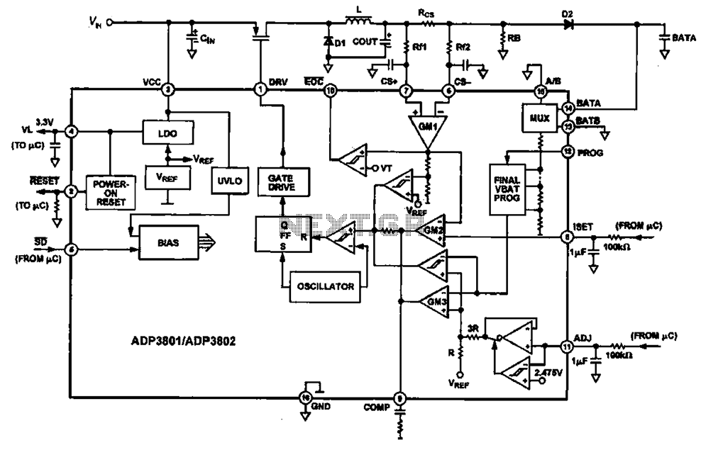
Charging circuit diagram for personal work based on the operating principle of ADP3801/3802 charging circuit. The ADP3801/3802 is a highly integrated battery charger controller designed for Li-ion and Li-polymer batteries. The charging circuit typically consists of several key components including...
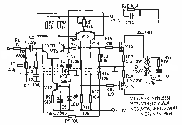
This article describes a transformer-based output FET amplifier, with tonal characteristics similar to those of tube amplifiers. It introduces various effects that are significant for audio enthusiasts. Power amplifier specifications include a rated output power of 50W (with an...