
Ophthalmology light lamp switch circuit

The remote-controlled light switch circuit is designed to provide efficient operation for various lighting applications, particularly in remote-controlled devices. The primary components include two transistors (VT1 and VT2), a relay (K), and light-sensitive resistors (RL1 and RL2). The circuit functions by utilizing the changes in light intensity to control the operation of the transistors and, consequently, the relay.
When the circuit is powered, the photosensitive resistor RL2 detects light from a flashlight or laser pointer. As light falls on RL2, its resistance decreases, triggering VT2 to conduct. This conduction energizes relay K, which locks the circuit in an "on" state, allowing lamp E to illuminate. The self-locking feature of the relay ensures that the light remains on until a specific condition is met for deactivation.
To turn off the light, the circuit relies on the second photosensitive resistor RI.1. When illuminated, RI.1's resistance drops, causing VT1 to conduct. This action decreases the base potential of VT2, leading to its cutoff and the deactivation of relay K. The opening of the relay contacts results in the light being turned off.
Diode VD2 plays a crucial role in stabilizing the circuit by ensuring that the base potential of VT2 is adequately raised, thus enhancing the reliability of the shutdown process. The power supply section, which includes a capacitor and rectifying diodes, ensures a stable voltage supply to the circuit, while resistors RP1 and RP2 allow for fine-tuning of light sensitivity, accommodating varying environmental conditions.
The choice of light-sensitive resistors is critical; they should exhibit a significant difference in resistance between light and dark conditions to ensure reliable operation. Moreover, the physical design of the light-sensitive cylinder is important to prevent interference from ambient light while maintaining effective operation during adverse weather conditions, such as rain.
Overall, this circuit is a versatile solution for remote control lighting applications, combining simplicity with effectiveness, and is well-suited for various electronic projects requiring remote activation and deactivation of lights.Is a light remote control light switch circuit, remote control toys can be sufficient flashlight or laser pointer. Use as long as the torch for a photo at the photosensitive resistor RL2, RI.2 resistance was low, VT2 immediately turned on,
the relay K suction units, the power station contacts kl closed circuit self-locking, the other a make contact k -2 close together allows the lamp E energize hair light. Turn off the lights when needed, just look again irradiated RI.1, RI.1 that is mutated to a low resistance, so that the rapid conduction VT1, VT1 conduction will VT2 base potential drop down, forcing VT2 cut iL, K release, its two make contacts jump, put out the lights off.
VD2 role is to raise the conduction VT2 base potential, is conducive to the irradiation RI.1 shutdown. The machine working power by the capacitor (1z buck, VD3 -VD6 rectifier, vs regulator and filter 1. [crossing supply .RP1, RP2 were used to control the lights and turn on the light sensitivity withered section operation.
RL1, RP2 are used M (; 45-type light-sensitive resistors, light resistance and dark resistance requirements differ multiples bigger the better, the production was a blessing when they acquired in hood to eliminate ambient light interference, but they should not be too light-shielding cylinder. deep and is too small, then the rain will bring remote operation described quasi difficult .K should work voltage, 12V, there are two sets of transfer of small electromagnetic relay exchange contacts, such as JRX-13F, DC12V type, etc.
.f, the pressure should be used 400v or more of LBB poly-ene-resistant capacitors, Wu other devices no special requirements,
Related Circuits
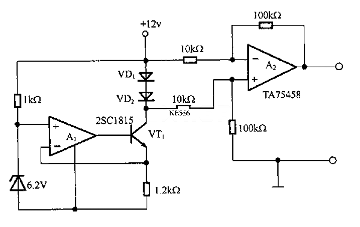
A diode is utilized in a temperature sensor application circuit. Silicon diodes VD1 and VD2 serve as the temperature sensors, exhibiting a temperature coefficient of silicon diodes. The circuit includes a constant current source, VT1, which provides a steady...
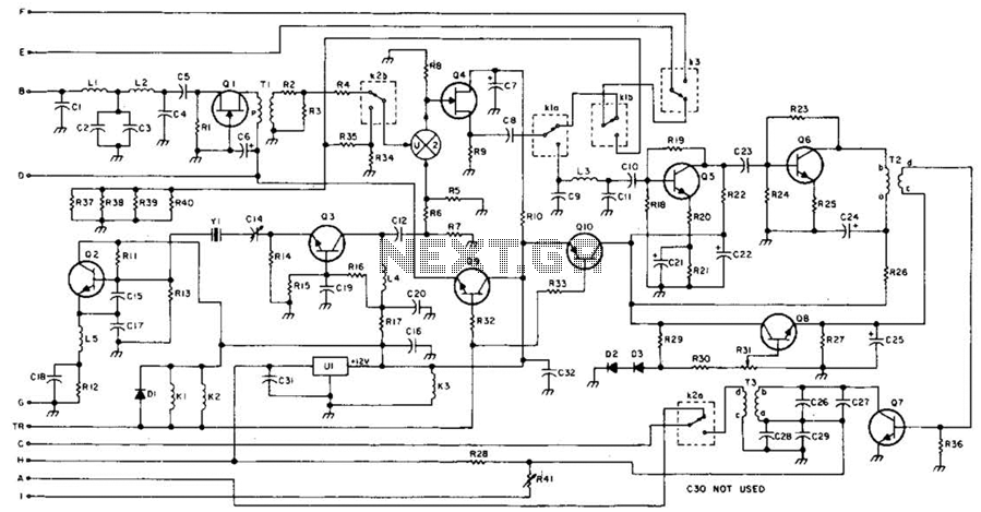
This 49-MHz FM transmitter comprises an audio amplifier, a low-pass filter, three RF stages, and a regulated DC power supply. The output power is approximately 16 mW into a 50-ohm load. This transmitter is suitable for various 49-MHz applications,...
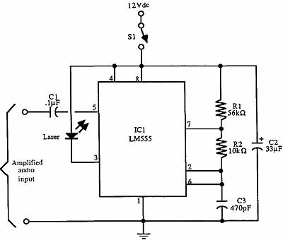
Due to the high frequency of light within the electromagnetic spectrum, it serves as a superior medium for communication compared to radio waves. Lasers are ideal for communication links because they produce a powerful and narrow beam that is...
This FM transmitter circuit employs four radio frequency stages: a VHF oscillator built around the transistor BF494 (T1), a preamplifier constructed with the transistor BF200 (T2), a driver using the transistor 2N2219 (T3), and a power amplifier based on...
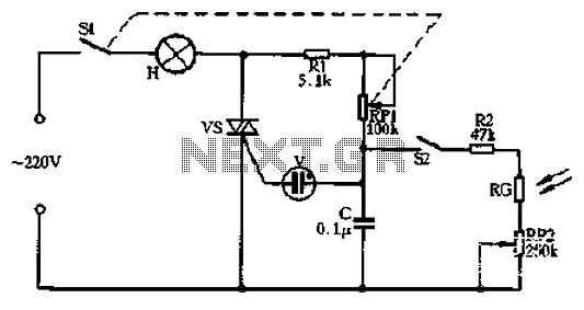
Circle S2 is a stable automatic light switch. When S2 is open, the entire circuit operates as a subsection II SCR stepless presentation dimmer, omitting the high-frequency filter circuit. The trigger diode switch activates a neon indicator bulb (V),...

This LED VU Meter (volume unit) is designed to monitor and display power levels present at the speaker terminals of a stereo audio power amplifier. The levels are represented in ten discrete steps using ten LEDs for each channel,...