
Optical Heart Rate Monitor

The heart rate monitor circuit employs an infrared LED and a phototransistor to detect variations in light intensity caused by blood flow in a fingertip. The IR LED emits infrared light, which penetrates the skin and reflects back to the phototransistor. The amount of light received by the phototransistor varies with the pulsation of blood, leading to changes in the output voltage.
The circuit is designed to amplify and filter the weak signals generated by the phototransistor. The output is connected to a 24-bit ADC, specifically the EMANT300 USB DAQ, which is capable of capturing low-level signals with high precision. This allows for effective digitization of the analog signal without the need for extensive external signal conditioning.
The software component of the heart rate monitor includes a class written in C#, which is responsible for processing the data collected from the ADC. The class implements algorithms for noise reduction and peak detection. It utilizes an autocorrelation function to identify the periodic peaks in the signal corresponding to heartbeats. The peaks are analyzed to compute the beats per minute (BPM) value. Any readings that deviate significantly from expected values due to noise or interference are filtered out to ensure accuracy.
The output waveform, as depicted in the accompanying figure, is subjected to software-based averaging to enhance signal clarity. This filtering process helps in minimizing the impact of noise, allowing for a more reliable heart rate measurement. Overall, the design illustrates a practical application of light sensors in biomedical monitoring, showcasing the integration of hardware and software in developing a functional heart rate monitoring system.In this application note, we create a heart rate monitor by using one IR LED and phototransistor pair and observing the waveform at the phototransistor output. This is intended for illustrating a typical light sensor application and not intended for actual medical use.
The accompanying video also shows the typical low level signals involved in this type of circuit and how the dynamic range from a 24 bit ADC EMANT300 USB DAQ allows such signals to be observed without further signal conditioning. When a finger is placed on the phototransistor, the voltage read rises above 0.3V. If a good contact is made, a sinusoidal type signal is observed. As the signal rides on a fluctuating DC signal, a simple differential signal is created. From maths, we know that when a max or min is reached, its differential value is zero. After this an autocorrelation function is applied and the peaks extracted to obtain the heart rate. When the signal is noisy, a wrong BPM will be calculated. Any count that is obviously wrong is ignored. This is all taken care of by the HRM class. The HRM class is written in C#. You can improve on it using the Visual C# 2005 Express. The figure below shows the filtered waveform seen at the phototransistor. The waveform is filtered by software using averaging. 🔗 External reference
Related Circuits

NE5532DR absolute maximum ratings: (1) Supply voltage: VCC+ 22 V; VCC-: -22 V; (2) Input voltage, either input VCC ±; (3) Input current: ±10 mA; (4) Duration of output short circuit: Unlimited; (5) Package thermal impedance, JA: D package...

The LM4844 is an integrated audio subsystem designed for stereo cell phone applications. Operating on a 3.3V supply, it combines a stereo speaker amplifier delivering 495mW per channel into an 8Ω load and a stereo OCL headphone amplifier delivering...

When the push button is pressed, a clock pulse appears on the CLK input of flip-flop IC1b. The output then toggles, causing the LEDs to turn off. Simultaneously, IC1a is reset, silencing the buzzer. Pressing the button again will...
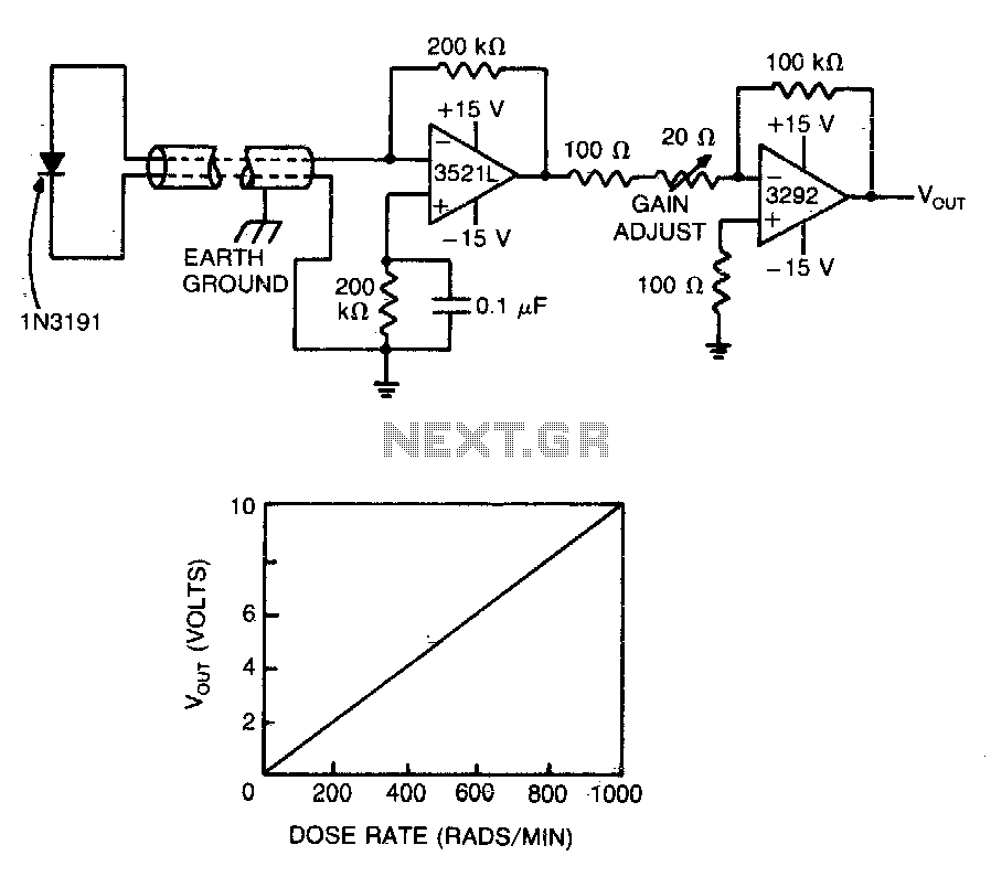
A commercial diode serves as the detector in this highly accurate radiation monitor. The low-drift FET-input operational amplifier amplifies the detector current to a usable level, while the chopper-stabilized amplifier provides additional gain, minimizing errors caused by fluctuations in...

This circuit provides emergency lighting during a power outage. The phototransistor should be positioned to maximize the coupling of both neon light and ambient light into the pellet, without allowing self-illumination from the 6-V lamp. Many circuits of this...

The transmitter operates by deriving its power directly from the AC line. The DC power required for the circuit is generated in two stages: the first stage powers the RF power amplifier, while the second stage supplies power to...