Optical-sensor-to-ttl-interface

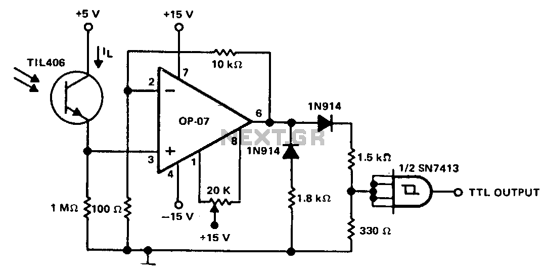
This circuit is designed to detect low light levels at the sensor, amplify the signal, and provide a TTL-level output. When the optical sensor detects low-level light, its output is small and must be amplified. An amplifier with very low input bias current and high input resistance is required to detect the "on" condition. When sensor TIIA06 is in the "on" condition, its output is assumed to be 250 nA (allowing for a safety margin). This results in a 250 mV signal being applied to the non-inverting input of amplifier OP-07. Due to the circuit configuration, the OP-07 provides a gain of 100, and its output is in positive saturation. The OP-07 output level is applied to a loading network that provides the basic TTL level.
The circuit operates as a low-light detection system, utilizing an optical sensor, specifically the TIIA06, which is sensitive to ambient light conditions. When light levels fall below a predetermined threshold, the sensor transitions to an "on" state, producing a minimal output current of approximately 250 nA. This current, while sufficient for detection, translates to a very low voltage signal of 250 mV. To effectively utilize this signal, it must be amplified for further processing.
The OP-07 operational amplifier is chosen for its low input bias current and high input impedance, making it ideal for interfacing with the TIIA06 sensor. The configuration of the OP-07 allows for a gain of 100, which significantly amplifies the input signal. In this setup, the non-inverting input of the OP-07 receives the 250 mV signal from the sensor, and the output of the amplifier reaches a level that is sufficient for TTL logic levels.
The output from the OP-07 is designed to enter positive saturation, ensuring that the signal is strong enough to be recognized as a high logic level by subsequent digital circuits. This output is then routed to a loading network, which is responsible for conditioning the signal to meet standard TTL voltage levels. The loading network may consist of resistors and capacitors that stabilize the output and ensure compatibility with other digital components in the system.
Overall, this circuit effectively converts low-level optical signals into a robust digital signal suitable for further processing in electronic systems, making it valuable in applications such as light-sensitive alarms, automated lighting systems, and other light detection mechanisms.This circuit is designed to detect a low light level at the sensor, amplify the signal, and provide a TTLlevet output. When the optical sensor detects low-levellight, on condition, its output is small and must be amplified.
An amp with very low input bias current and high input resistance must be used to detect the on condition. When sensor TIIA06 is in the on condition, its output is assumed to be 250 nA (allowing a safety margin).
This results in a 250-m V signal being applied to the noninverting input of amplifier OP-07. Because of the circuit configuration, the OP-07 provides a gain of 100 and its output is in positive saturation. The OP-07 output level is applied to a loading network that provides the basic TTL level.