
oscillation Oscillator circuit
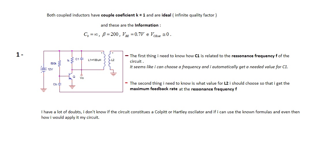
In electronic oscillators, the relationship between capacitance and resonance frequency is crucial. In a Colpitts oscillator, the resonance frequency is determined by the inductance (L) and the equivalent capacitance (Ceq) formed by the capacitors in the circuit, which typically include C1 and another capacitor in series or parallel. The formula for the resonance frequency (f) is given by:
f = 1 / (2π√(L * Ceq))
For a Colpitts oscillator, Ceq can be calculated using the formula:
Ceq = (C1 * C2) / (C1 + C2)
where C2 is the additional capacitor in the circuit. By selecting a desired frequency, the appropriate value for C1 can be derived by rearranging this equation, allowing for the calculation of C1 based on the known values of L and C2.
In contrast, a Hartley oscillator also employs inductors and capacitors to generate oscillations, but it typically uses a tapped inductor and a single capacitor for frequency determination. The resonance frequency for a Hartley oscillator is expressed as:
f = 1 / (2π√(L * C))
where L is the total inductance and C is the capacitance in the circuit. To identify whether the circuit is a Colpitts or Hartley oscillator, one must analyze the configuration of the components. If the circuit features two capacitors in a specific arrangement, it is likely a Colpitts oscillator. If it has a tapped inductor with a single capacitor, it is likely a Hartley oscillator.
Understanding the configuration and applying the appropriate formulas will clarify the relationship between C1 and the resonance frequency, enabling effective design and implementation of the oscillator circuit.The first thing I need to know how C1 is related to resonance frequency f of the circuit. It seems like I can choose a frequency and I automatically get a needed value for C1. I have a lot of doubts I don`t know if the circuit constitutes a Colpitts or Hartley oscillator and if I can use the known formulas and then how I would apply it my circuit. 🔗 External reference
Related Circuits
The circuit is designed exclusively for fundamental crystals, as it lacks mode suppression components. The oscillator transistor Q104 remains in a cutoff state for most of the time, activating only briefly during the peak of the crystal current waveform....
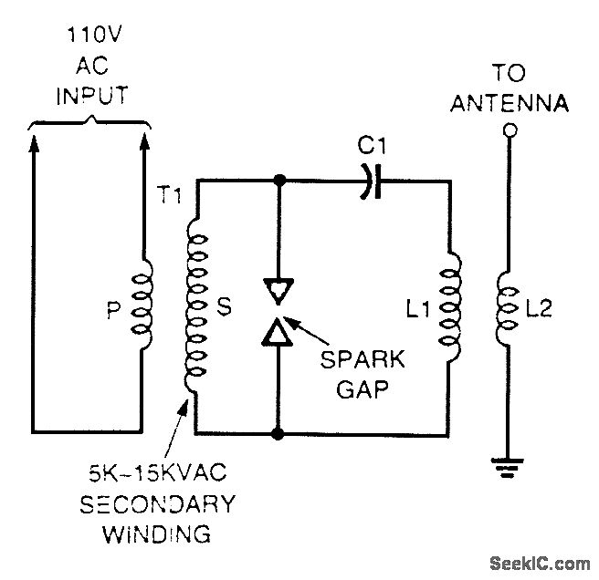
A high-voltage current-limiting transformer (T1) provides power to a basic LC tuned circuit. As capacitor C1 charges to approach the maximum output voltage of the transformer, the air gap in the spark gap breaks down, thereby completing the circuit...
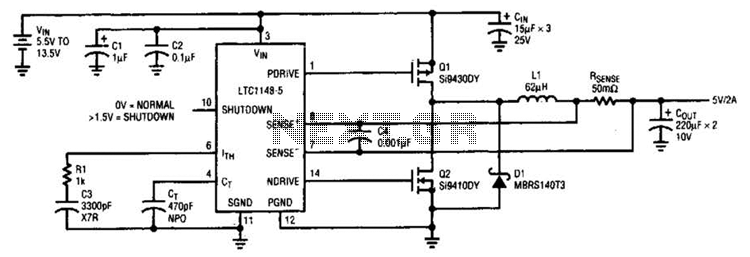
A typical LTC 1148 surface-mount application provides 5 V at 2 A from an input voltage range of 5.5 V to 13.5 V. The operating efficiency, illustrated in B, peaks at 97% and remains above 90% from 10 mA...
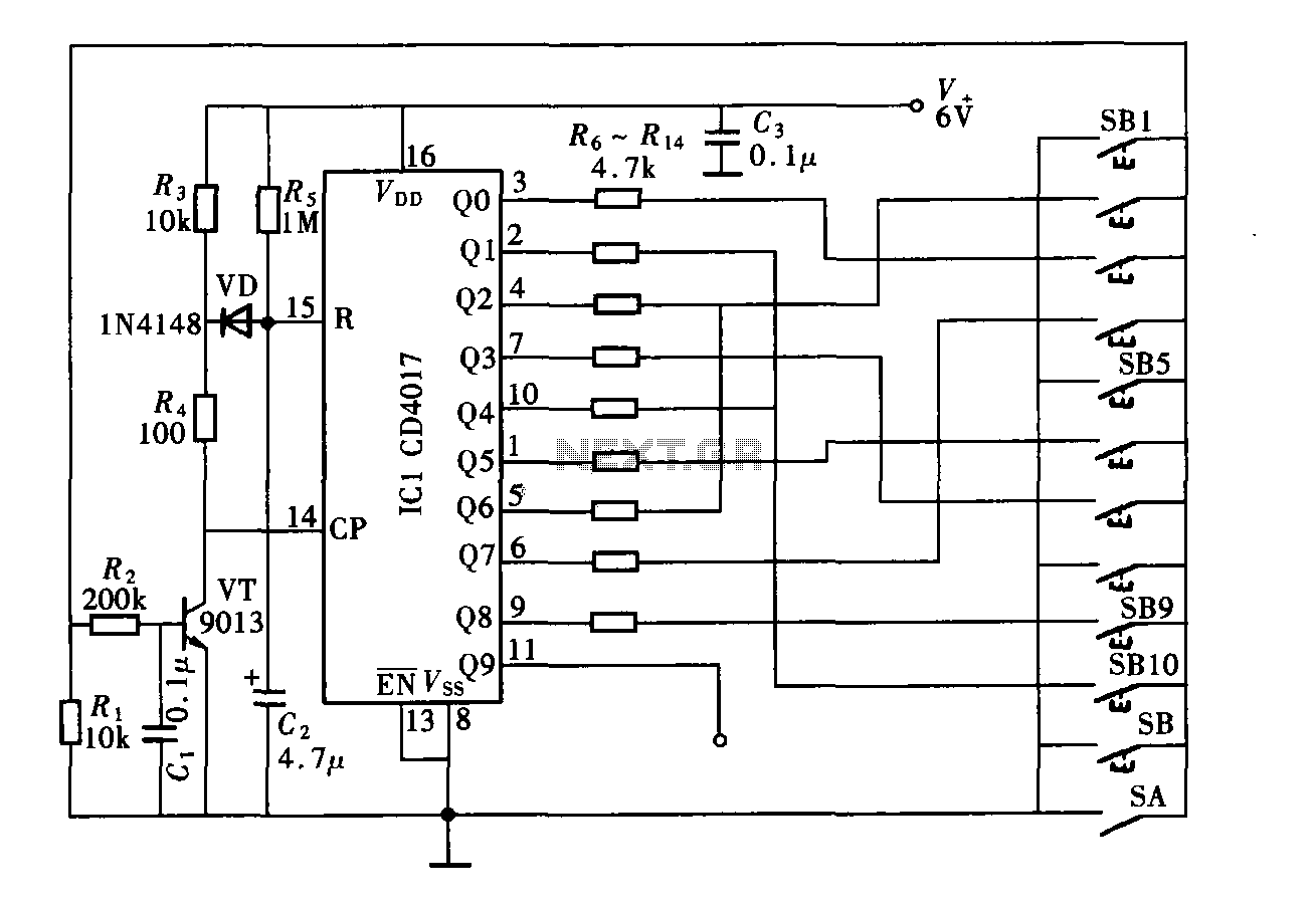
The digital controller features a nine-digit password system and includes a total of 11 keys. This comprises four pseudo-code keys and seven overlay keys, each of which has two valid key options. The total number of possible passwords is...
This page is provided to the domain owner free by Sedo's Domain Parking. Disclaimer: The domain owner and Sedo maintain no relationship with third-party advertisers. References to any specific service or trademark are not controlled by Sedo or the...
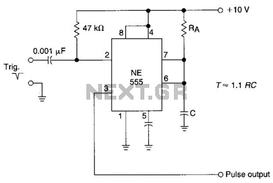
The time constant of RAXC determines the period of the monostable multivibrator. A negative pulse at pin 2 of the 555 starts the cycle. The monostable multivibrator is a circuit configuration that produces a single output pulse in response...