
Oscillator configuration in transmitter
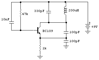
The oscillator circuit for an AM transmitter typically serves as the primary signal generator, producing a carrier wave that is modulated with audio information. This circuit often employs a combination of active and passive components, including transistors, capacitors, resistors, and inductors, to create oscillation at the desired frequency.
In a basic design, the oscillator may utilize a transistor in a common-emitter configuration. The input signal is fed into the base of the transistor, where it is amplified. Feedback is provided through a network of resistors and capacitors, which determines the oscillation frequency. The output is then coupled to an LC (inductor-capacitor) tank circuit that helps to filter and stabilize the oscillation, ensuring a clean carrier wave.
For AM transmission, the modulated signal is generated by varying the amplitude of the carrier wave in accordance with the audio input. This modulation can be achieved using a simple variable resistor in series with the audio signal, allowing the amplitude of the carrier wave to change as the audio signal varies.
Careful consideration must be given to component values to ensure the oscillator operates within the desired frequency range and maintains stability under varying conditions. Additionally, the design may include tuning elements to allow for frequency adjustments, which is essential for compliance with broadcasting regulations and for optimizing transmission quality.
Overall, the oscillator circuit is a fundamental component of AM transmitters, playing a crucial role in the generation and modulation of radio frequency signals.Hi Expert, I recently receive some question on an oscillator in some AM transmitter. I searched the web and find this circuit. According to author,.. 🔗 External reference
Related Circuits
This circuit is a conventional Pierce type oscillator that utilizes a JFET. It operates with fundamental mode crystals and exhibits good performance and reliability when a low noise JFET is employed. The feedback is regulated by the capacitance of...
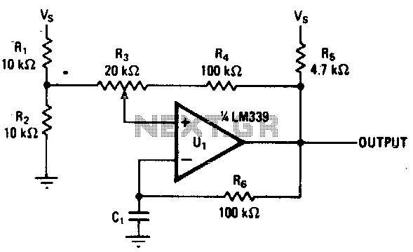
Varying the amount of hysteresis in this comparator circuit allows for smooth adjustment of output frequencies within the range of 740 Hz to 2 kHz. The hysteresis level, in combination with the time constant formed by resistor R6 and...
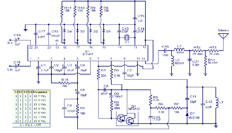
The circuit presented is a high-quality Stereo FM transmitter capable of transmitting signals up to a range of 70 feet. It utilizes the BH1417 PLL stereo transmitter IC from Rohm Semiconductors, which features separate audio processing sections for left...

The pressure transmitter circuit data acquisition system utilizes the 1B31, an 18-bit A/D converter (AD1170), and an MCS-51 microcontroller. The configuration, as depicted in the accompanying diagram, features a full-scale output voltage of 10 mV from the pressure transmitter...
This compact transmitter employs a Hartley-type oscillator. Typically, the capacitor in the tank circuit would connect to the base of the transistor; however, at VHF frequencies, the base-emitter capacitance of the transistor behaves like a short circuit, effectively maintaining...
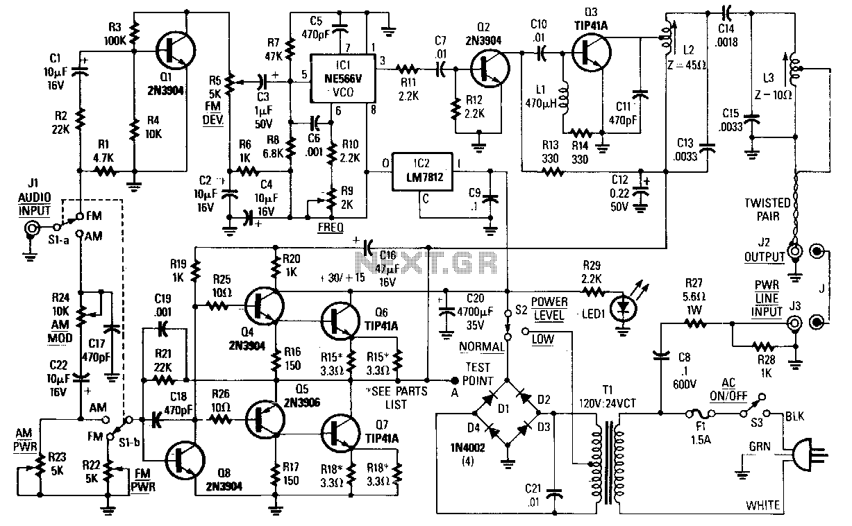
The choice between AM, narrowband FM (less than 15 kHz), or wideband FM (greater than 30 kHz) is determined by the specific application. FM is preferable for music transmission due to its superior noise immunity. For speech or other...
Warning: include(partials/cookie-banner.php): Failed to open stream: Permission denied in /var/www/html/nextgr/view-circuit.php on line 713
Warning: include(): Failed opening 'partials/cookie-banner.php' for inclusion (include_path='.:/usr/share/php') in /var/www/html/nextgr/view-circuit.php on line 713