Wireless keyboard circuit
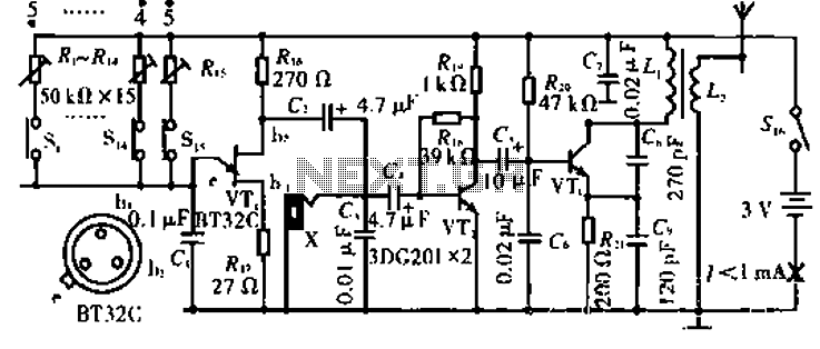
Description: The circuit operates with VT3 and associated components arranged as a common-base capacitance feedback oscillation circuit. The oscillation frequency is set by capacitors C8, C9, and inductor L1. VT2 serves as a voltage amplification stage that reinjects the audio signal at a high amplitude into the high-frequency signal, which is amplitude modulated by the high-frequency signal generated by L2.
The described circuit utilizes a common-base configuration for VT3, which is effective in providing high-frequency oscillations. The oscillation frequency is critically determined by the values of capacitors C8 and C9 in conjunction with inductor L1, which forms a resonant tank circuit. This tank circuit is essential for establishing the desired frequency of oscillation, allowing for precise tuning of the circuit's output.
VT2, functioning as a voltage amplification stage, plays a crucial role in enhancing the amplitude of the audio signal before it is fed back into the circuit. This feedback mechanism is vital for maintaining the oscillation and ensuring the stability of the output signal. The modulation of the high-frequency signal by the audio input is achieved through the interaction with L2, which serves as a coupling inductor, facilitating the transfer of energy and information between the high-frequency oscillator and the audio signal path.
The overall design of this circuit is particularly suited for applications requiring amplitude modulation of audio signals, such as in communication systems or audio processing equipment. The careful selection of component values and the configuration of the circuit elements are paramount for achieving optimal performance, including desired frequency response and signal integrity.Circuit works:, VT3 and peripheral components configured as a common-base capacitance feedback oscillation circuit, the oscillation frequency is determined by C8, C9, L1. VT2 voltage amplification stage, and put back the audio signal with a large amplitude to the high frequency signal VT3 is amplitude modulated with high frequency signal emitted by the L2.
