
Pattern generator
Technical Specifications - Characteristics
Working voltage: 9 VDC
Current drawn: 2 mA
Operating Frequency: 170 - 250 MHz (VHF)
Horizontal scan frequency: 16525 Hz
Vertical scan frequency: 50 Hz
Output impedance: 75 ohm
How it Works
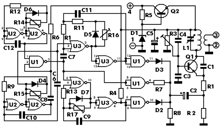
The circuit can be divided into five distinct stages: four astable multivibrators and an output stage built around a VHF oscillator. The first astable multivibrator consists of two NOR gates in U2, along with components R9, R15, D4, C8, and C10. These two NOR gates function as inverters, forming an astable multivibrator that oscillates at a frequency of 16525 Hz, corresponding to the horizontal scan frequency of the television. This frequency can be fine-tuned using R15. Capacitor C10 provides the necessary feedback to sustain the oscillations. The signal from the output of this oscillator is transmitted through C8 and R6 to the output stage, where it modulates the signal.
The second multivibrator, constructed from the remaining two NOR gates in U2, along with R12, R14, D6, and C12, generates the pulses required for the vertical scanning frequency of 50 Hz. This frequency is directed to the input of one of the AND gates in U1 (pin 1). Another multivibrator, formed by two NOR gates in U3 along with components R13, R17, C9, and D7, creates pauses between pulses. These pauses are then fed to the AND gates in U1 (pins 8, 9, and 10), which are configured as inverters. This modulation results in the appearance of vertical stripes (bars) on the TV screen.
The final multivibrator, consisting of the last two NOR gates in U3 along with components R1, R11, R16, C7, and D5, produces the pulses that manifest as horizontal lines on the screen.
This circuit design effectively allows for the generation of a visual pattern that can be utilized for aligning the timing circuits of television receivers, ensuring optimal performance and synchronization. The careful arrangement of multivibrators and oscillators facilitates the precise generation of the necessary frequencies for both horizontal and vertical scanning, making it an essential tool in television servicing and repair.A pattern generator is a very useful instrument for the correct alignment of the timing circuits of a television set. The circuit we propose you to build, is a «bar generator» that will produce horizontal and vertical stripes (bars) on the TV screen, that will help you align the vertical and horizontal scanning synchronisation circuits of the receiver.
Technical Specifications - Characteristics
Working voltage: ................... 9 VDC
Current drawn: ...................... 2 mA
Operating Frequency: ........... 170 - 250 MHz (VHF)
Horizontal scan frequency: ... 16525 Hz
Vertical scan frequency: ....... 50 Hz
Output impedance: ............... 75 ohm
How it Works
The circuit can be divided in five different stages. Four astable multivibrators and the
output stage which is built around the VHF oscillator.
The first astable consists of two NOR gates in U2 and the components R9, R15, D4, C8,
and C10. The two NOR gates are used as inverters and together they form an astable
multivibrator which oscillates at a frequency of 16525 Hz, which is the horizontal scan
frequency of the TV, and can be fine-tuned by means of R15.
The capacitor C10 is there
to provide the necessary feedback to maintain the oscillations. The signal from the output
of the oscillator is taken through C8 and R6 to the output stage and modulates it.
The other multivibrator built around the other two NOR gates in U2, together with R12,
R14, D6 and C12 produces the necessary pulses for the vertical scanning frequency which
is 50 Hz. This frequency is fed to the input of one of the AND gates in U1 (pin 1).
The multivibrator built around two of the NOR gates in U3 and the components R13, R17,
C9 and D7 produces the pauses between pulses, which after being fed to the AND gates
in U1 (pins 8, 9 and 10) which are connected as inverters are then also used to modulate
the oscillator and appear on the TV screen as vertical stripes (bars).
Finally the last multivibrator which consists of the remaining two NOR gates in U3 together
with the components R1, R11, R16, C7 and D5 produces the pulses which appear on the
screen as horizontal lines.
🔗 External reference
Related Circuits
PWM waveforms are frequently employed to regulate the speed of DC motors. The mark/space ratio of the digital waveform can be established either by utilizing an adjustable analog voltage level (as seen in a NE555-based PWM generator) or through...
Quartz crystals exhibit a unique property whereby their amplitude and phase characteristics repeat at frequencies that are uneven multiples of the fundamental frequency. Quartz crystals are widely utilized in electronic circuits due to their ability to generate precise frequencies. This...
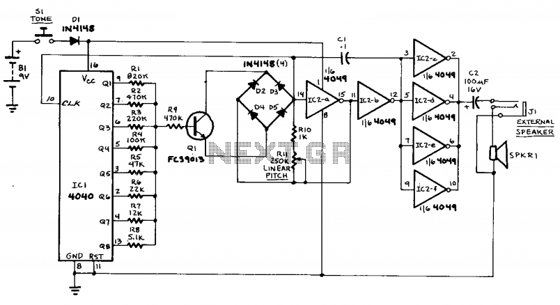
This circuit can generate sounds such as a European police-car siren, bird noises, and spaceship sounds. It can also function as a doorbell or an alarm. The circuit consists of four main components: a binary counter, a digital-to-analog (D/A)...
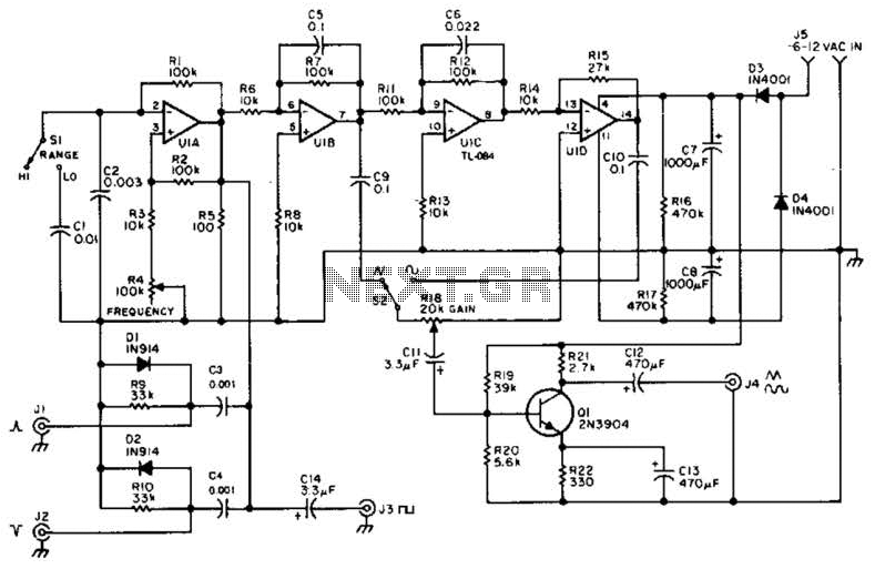
A quad op-amp serves as the core component of this function generator. U1A produces a square wave, which is outputted to J8. J1 and J2 are pulse outputs derived from differentiating the square wave. The integrator U1B creates a...

This low-cost function generator, based on the Maxim MAX038 high-frequency waveform generator, produces sine, triangle, and square waves from under 1 Hz to over 20 MHz. The function generator utilizing the Maxim MAX038 is designed to provide a versatile range...
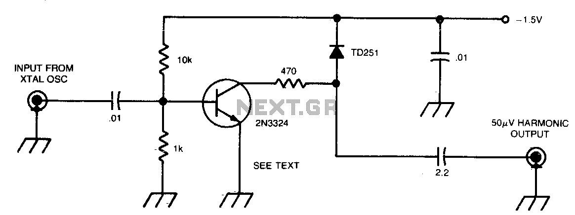
This circuit generates 50 µV harmonics at frequencies up to 1296 MHz, utilizing an input voltage of 0.5 to 1 V from a 100 or 1000 kHz crystal oscillator. By employing a germanium diode instead of a tunnel diode,...