
PC-Midi Interface
The circuit design for the PC soundcard MIDI interface incorporates several essential components to ensure functionality and reliability. It begins with the integration of MIDI sockets, typically five in total, which allows for multiple MIDI connections. Each socket connects to the main circuit via a series of resistors and buffers, ensuring signal integrity and preventing data loss during transmission.
The optocoupler plays a critical role in isolating the MIDI signals, protecting both the MIDI devices and the soundcard from potential electrical interference. The addition of the resistor from pin 7 of the optocoupler to ground is crucial for stabilizing the MIDI In signal, as it helps to mitigate noise and ensures a reliable connection.
Power is supplied directly from the soundcard, eliminating the need for external power sources and simplifying the design. The circuit also features a straightforward layout that allows for easy assembly on a stripboard, with clear indications for where to make connections and adjustments.
To enhance the user experience, the design can be modified to include a "thru" function, which allows the MIDI signals to be passed through to other devices without interruption. This flexibility is particularly useful for musicians who require seamless integration of multiple MIDI instruments or controllers.
Overall, this MIDI interface design is a practical solution for PC users looking to expand their sound capabilities, providing a reliable and efficient means of connecting MIDI devices to their soundcards. The emphasis on user-friendly assembly and potential modifications makes it an attractive option for both novice and experienced electronics enthusiasts.This design is for PC Soundcards obviously. If you need an interface for a Mac see my other page. For other computers and PCs without a soundcard you might take a look at Harmony Central`s interface page. I have built one of these myself, exactly as described, so I know this design works. However, I make no promises that you will be able to do likewise, or that I will be able to help you if yours doesn`t work.
I don`t mind trying to help if you contact me, and most people who have done so have managed to get their interface going. It is also worth noting that Jim Rowe (of Electronics Australia and more recently with Silicon Chip - both Australian electronics magazines) has published two versions of a similar circuit.
These are available (by mail order if required) as kits from a number of Australian electronics stores. Dick Smith Electronics may still have the original version `MIDI Breakout Box` kit. It may even be cheap (with limited stock) as it`s been superceded. The newer version, `MIDI Mate` is a far neater design with a very nice box and front label (in my opinion).
Jaycar Electronics has the full kit (all hardware including printed circuit board) for this project for AUD$39. 95 and it can be ordered from them by email. Dick Smith will probably also have the later version as well although I haven`t checked this. (Please note: I have absolutely no affiliation with Dick Smith or Jaycar). Important note: I recently built one of these `MIDI Mate` kits for a friend. The MIDI In port did not work reliably. Neither of these kits have a resister from pin 7 of the optocoupler to ground. The addition of this resistor to the board fixed the problem (the reason for my inclusion of this resistor in all my designs is mentioned in the Mac version ) I also take absolutely no responsibility for computer or midi equipment which might be damaged during your efforts to build this device and get it working.
It is theoretically possible for this to occur, especially if you connect the wires to the computer incorrectly, although it appears to be unlikely as none of the many people who have contacted me have run into any problems so far. Most PC Soundcards have midi capability these days and the connections are provided via the joystick port.
You still need an interface, however, but because part of the `interface` is already provided in the soundcard the circuit I am about to describe is often referred to as a `breakout box`. It became obvious after some reading that with a few modifications to my previous Mac interface design, a suitable circuit for a PC could even more easily be built.
There is no need for stealing power from the data transmission lines (as there is with the Mac) since +5V is supplied by the soundcard. There is also no need for an external clock circuit. Deleting these sections, changing a few links and resistor values, and using the extra buffers for a `thru`, I came up with the following circuit which worked first go!
If you build the thing with the five midi sockets as shown above, you might have a hard time finding a box to fit exactly since there are sockets on both sides of the board. One solution is to use chasis mount sockets instead of PC mounted ones as I did but this requires separate wiring to each socket which is a bit less tidy.
Another solution would be to increase the number of strips (width) of your stripboard so that the sockets fit exactly within your box. This would obviously require you to increase the lengths of the link and resistor (R8) to J5 which is no big deal.
Yet another solution is to forget about the third Out and use that socket for the Thru. It is possible to include a 15 pin `D` socket as well to avoid the need for swapping midi interface 🔗 External reference
Related Circuits
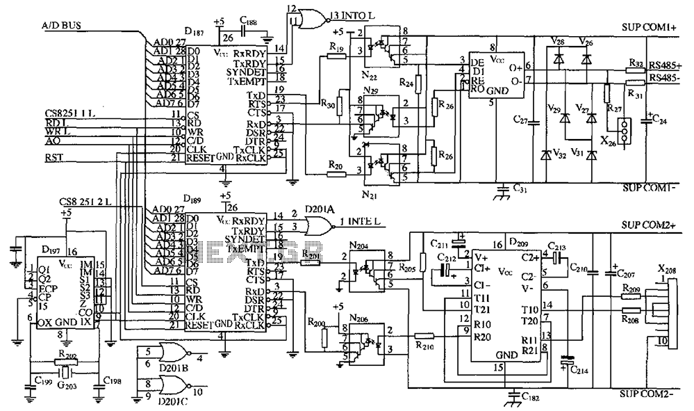
As shown in the figure, D187 is a universal asynchronous receiver-transmitter (UART). Its RX/TX signals are received through optocouplers N21, N22, and N29, facilitating RS-485 communication. The interface receiver/transmitter D28 and microprocessor D211 are completely optically isolated. D197 serves...
Face Through attendance is the world's first embedded facial recognition machine, with an error rate of less than one in one hundred thousand and a rejection rate of less than one percent. In the field of biometrics, this device...
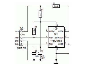
Many modern motherboards are equipped with an infrared data interface compliant with the IrDA standard, but this interface is not very often used. The infrared data interface, adhering to the Infrared Data Association (IrDA) standard, provides a wireless communication...
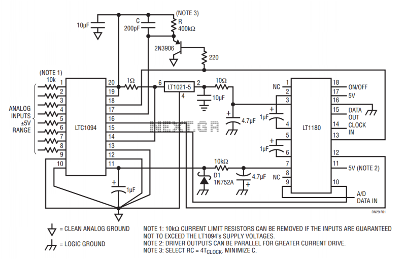
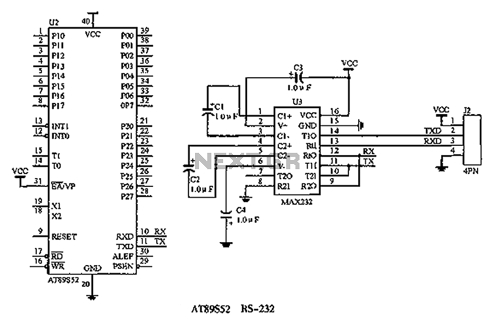
The LT1180 RS232 transceiver includes a charge pump which produces low ripple supplies with sufficient surplus current to drive a CMOS A to D converter and precision voltage reference. The circuit operates from a single 5V supply and draws...

A low-cost, low-part-count MIDI to Trigger interface with 10 outputs. This MIDI to Trigger interface generates a TTL (5V) trigger signal for each note across a range of ten notes. It can be utilized, for instance, as a MIDI...
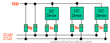
The I2C bus employs a bi-directional Serial Clock Line (SCL) and Serial Data Line (SDA). Both the SCL and SDA lines are pulled high using a pull-up resistor (Rp). An optional resistor (Rs) is utilized for ESD protection in...