Peak-db-meter

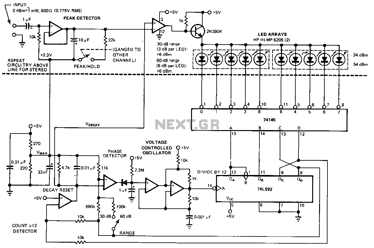
This circuit compares a rectified input voltage with a voltage that decays exponentially across a 4.7 kΩ resistor and a 0.01 µF capacitor. The comparison of the exponentially decaying voltage with the rectified input provides a peak-level indication that requires no adjustment. A phase-locked loop controls the scan rate so that each LED represents 6 dB within a 30 dB range.
The described circuit functions as a peak-level indicator using a rectified input voltage. The rectified voltage is compared against a reference voltage that is derived from an RC (resistor-capacitor) network, specifically a 4.7 kΩ resistor in series with a 0.01 µF capacitor. This RC combination creates an exponential decay response, allowing the circuit to measure transient signals effectively.
The operation begins with the rectification of an AC signal, which produces a pulsating DC voltage. This voltage is then fed into a comparator circuit that assesses its level against the exponentially decaying voltage produced by the RC network. As the input voltage rises, it will exceed the decaying voltage, triggering an output response that indicates the peak level of the input signal.
The phase-locked loop (PLL) integrated into the circuit plays a crucial role in controlling the scan rate of the output indicators, typically represented by LEDs. The PLL ensures that the scan rate is stable and synchronized with the input signal, allowing each LED to light up in increments that correspond to a 6 dB change in signal level. Given a total dynamic range of 30 dB, this results in five distinct LED indicators, providing a clear visual representation of the input signal's amplitude.
Overall, this circuit design is advantageous for audio applications, where monitoring signal levels is critical. The use of an RC network for voltage decay combined with the PLL for accurate timing ensures that the peak-level indication is both responsive and reliable, without necessitating manual adjustments.This circuit compares a rectified input, f."!N, with a voltage that decays exponentially across a 4. 7-KO resistor and a ·o.Ol-I"F capacitor. Comparing the exponentially decaying voltage with the rectified input provides a peak-level indication that requires no adjustment. A phase-locked loop controls the scan rate so that each LED represents 6 dB in the 30 dB range.