
PF Test Equipment

The transformer ratio-arm bridge circuit serves as an essential tool for evaluating the performance of insulation materials by measuring their capacitance and power factor. The circuit's design allows for precise adjustments to account for variations in the capacitive and resistive components of the insulation under test. The application of voltage to both the reference capacitor and the insulation under test ensures that accurate readings can be obtained when the circuit is balanced. The inclusion of a multi-winding transformer enhances the circuit's sensitivity and accuracy, making it suitable for a wide range of testing applications.
The models mentioned, such as the CB-100 and Delta-3000, exhibit varying levels of automation and user interface sophistication, catering to different testing needs. The manual balancing feature of the CB-100 allows for hands-on operation, while the Delta-3000's automatic balancing streamlines the testing process, making it more efficient and user-friendly. The digital displays in these models provide clear and immediate feedback to the operator, facilitating quick decision-making during testing.
The theoretical framework underlying the measurements taken by the MEU test set is crucial for understanding the principles of dielectric testing. By measuring the total current and utilizing a balancing network, the test set can accurately isolate the resistive component of the current, which is essential for calculating the power factor. The ability to adjust the milliwatt reading to achieve a minimum indicates that the capacitive reactance has been effectively canceled, allowing for reliable assessment of dielectric loss.
Overall, the transformer ratio-arm bridge circuit and associated test sets represent a sophisticated approach to insulation testing, ensuring that electrical components can be evaluated for their reliability and performance in various applications. The attention to detail in both the design and operation of these systems underscores their importance in maintaining the integrity of electrical infrastructure.A transformer ratio-arm bridge circuit is used as shown in the simplified diagram of Figure1. The circuit consists of a standard reference capacitor (CS) and the insula- tion under test (CX). A special multiwinding transformer is the characteristic feature of the circuit. A voltage is applied to bothCSandCX. The ratio arms, NSandNXare adjusted to balance capacitive current, and the variable resis- tor (RS) is adjusted to balance resistive current. The null indicator is used to determine when the bridge circuit is balanced. The values ofNSandNXare used to determine capacitance and the value ofRScorrelates to power (dissipation) factor of the test insulation. Model CB-100 is a low voltage (LV) bridge which is manually balanced for both capacitance and DF, but it is direct reading.
The semiautomatic models require manual balancing for capacitance, but they provide a direct digital readout of DF. Model Delta-3000 is automatic balancing for both capacitance and PF, and can also display DF directly (Figure 2).
It is simple to operate, providing automatic balancing and digital display for voltage, current, dielectric loss (in watts), capacitance, and PF. Readings are adjusted to equivalent values of 10 or 2. 5 kV The formulas used for calculating the PF or DF are illustrated by using an example (Figure 3) with an insulation of PF = 1.
0%. The value of PF is given by the cosine of the q angle, or the equation can be written as For specific operating instructions for any Megger test set, the reader is advised to follow the instructions given in the appropriate test set operating manual. This section briefly describes the Doble Engineering Company test equip- ment, its theory, and operation for performing PF tests.
The description of theory and operation is based on the MEU test set, but the theory and opera- tion of the other test sets is the same for all test sets as manufactured by Doble Engineering. The type MEU test set has special measuring circuit in which the total current (IT) of the insulation specimen is measured.
Then a balancing network is switched into the measuring circuit and the capacitive component (IC) of the specimen current is balanced out. The in-phase compo- nent ( IR ) of the specimen current is then measured. The formulas used for calculating the PF or DF are illustrated by using the example of Figure 3. 4 with an insulation of PF of 1. 0%. The value of PF is given by the cosine q, or the equation can be written as given below for the 6. Specimen loss is measured by turning the milliwatts-adjust which cancels the capacitive reactance. When the capacitive reactance is cancelled the meter will be at minimum reading. This meter reading and the proper multiplier provides the milliwatt for the dielectric loss in the insulation.
7. The capacitance of the specimen is automatically obtained as a prod- uct of capacitance multiplier and capacitance dial reading at mini- mum milliwatts balance. 9. The power supply polarity is reversed to cancel the effect of electro- static interference. The average of the two milliwatts results is calcu- lated as the specimen milliwatts loss. 10. The test set has shielding to minimize the effect of electrostatic interference, as well as electromagnetic interference.
For cases where high interference is encountered, a special interference cancellation circuit is available with the 10 kV test sets from Doble Engineering. The more advanced design of the Doble M4000 test set does not require inte 🔗 External reference
Related Circuits
The DZ-2 was developed by RCA in Camden, NJ, for the U.S. Navy to function as a Radio Direction Finder in naval aircraft. With a contract date of June 30, 1939, the receiver exemplifies pre-war design. It operates using...
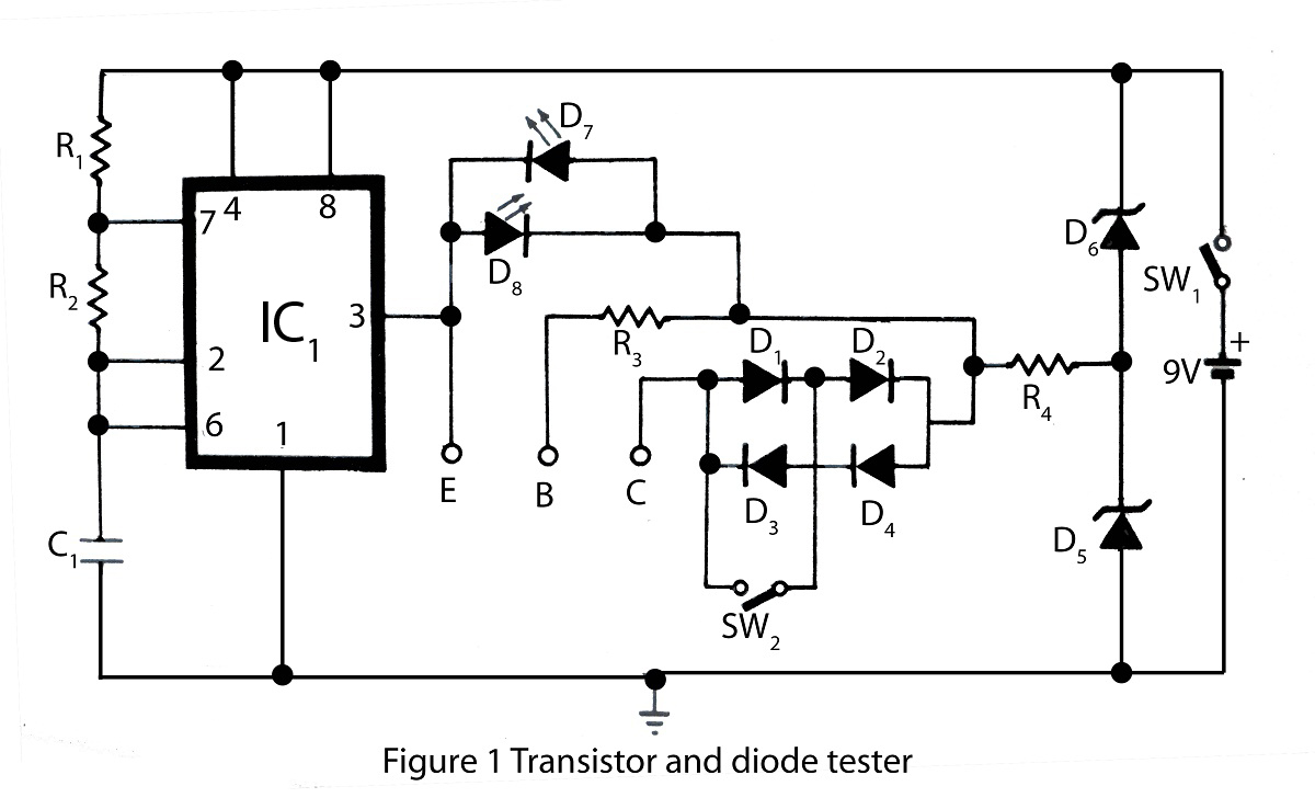
The transistor and diode tester available on this website is specifically designed for testing all types of transistors. Utilizing the principles of diode testing, it can also be used to check diodes. Various types of testing circuits can be...
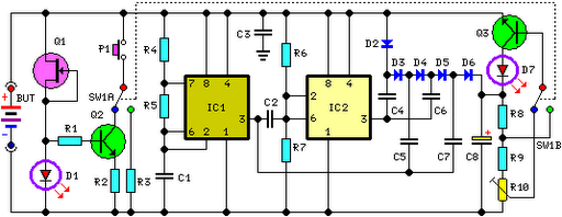
FET Q1 functions as a constant current generator, providing biasing for LED D1 and the base of Q2. This configuration ensures that D1 emits light at a consistent intensity, regardless of the battery voltage, which ranges from 3 to...
This is a convenient design for a transistor tester. The advantage of this circuit is that transistors can be tested without actually doing the circuit soldering. The tester uses two ICs: an NE 555 timer and a CMOS IC...
Tests 1.5 to 15 Volt cells. This circuit runs a fast battery test without the need of power supply or expensive moving-coil voltmeters. It features two ranges: when SW1 is set as shown in the circuit diagram, the device...
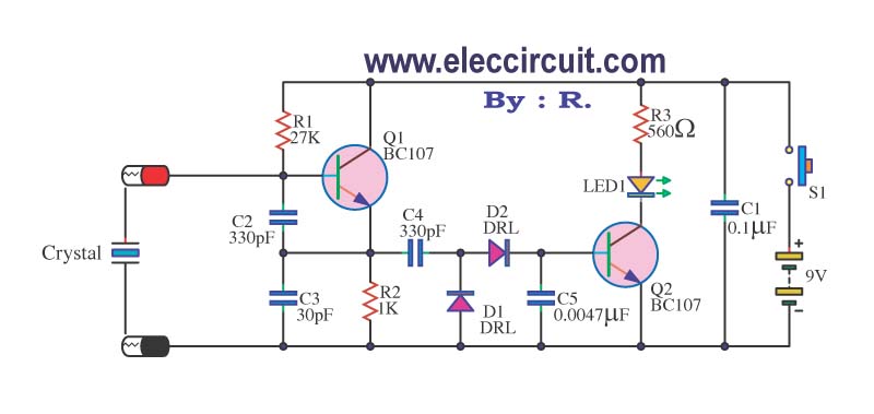
A multimeter cannot be used to test a crystal oscillator. Instead, a dedicated circuit is required, capable of checking crystals within the frequency range of 100 kHz to 900 MHz. This circuit is easy to construct and cost-effective. To construct...