
Phase reversal detector

A three-phase motor will run in the forward direction for three of these combinations, while for the remaining three, it will operate in the reverse direction. The circuit is capable of detecting all three reverse combinations. This circuit can be integrated into any existing motor starter, allowing the operator to verify whether the phase sequence has been altered before starting the machine.
The described circuit utilizes a phase sequence detection mechanism that is critical in three-phase motor applications. The arrangement ensures that the motor operates correctly based on the established phase sequence of VA-VB-VC. The connection of T1 to phase A and T2 to phase B is essential for the proper functioning of the circuit. The capacitor plays a pivotal role by advancing the voltage from phase B by 60 degrees, which is necessary for the comparison with the voltage from phase A.
The voltages across R2 are monitored to determine the phase relationship. When the voltages are in phase, the resultant voltage across R2 approaches zero, which keeps the neon lamp off, indicating that the phase sequence is correct. Conversely, if T2 is mistakenly connected to phase C, the resulting voltage across R2 will increase significantly, leading to the activation of the neon lamp. This serves as a visual alert that the phase sequence is reversed, which could potentially damage the motor if it were to be operated under these conditions.
The circuit's design allows for six different configurations of motor terminal connections to the three-phase supply. Out of these, three configurations will allow the motor to run in the forward direction, while the remaining three will cause it to run in reverse. The ability to detect all three reverse combinations ensures that operators are informed of any incorrect phase connection before initiating motor operation, thereby enhancing operational safety and preventing equipment damage. This circuit can be effectively integrated into existing motor starters, enhancing their functionality and providing a straightforward means of phase sequence verification.Assume the correct phase sequence to be VA-VB-VC. The circuit terminals are connected such that Tl gets connected to phase A and T2 to phase B. The capacitor advances the voltage developed across R2 due to phase "B" by — 60°, while the voltages developed across it by phase "A" is in phase with VA as shown in Fig. 69-1. The net voltage developed across R2 ~ zero, the neon lamp is not energized, thereby signaling correct phase sequence.
If terminal T2 gets connected to phase C, a large voltage, K(VA + Vc 60°), gets developed across R2, energizing the neon indicator to signal reverse phase sequence. The motor terminals can be connected to the three phases in six different combinations. A three-phase motor will run in the forward direction for three such combinations, while for the other three it will operate in the reverse direction. As shown in the table, the circuit detects all three reverse combinations. This circuit can be wired into any existing motor starter where the operator can see whether the phase sequence has been altered, before starting the machine.
Related Circuits
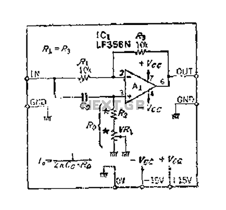
An accurate phase shift of 90 degrees can be achieved using a variable resistor (VR) and an operational amplifier (op-amp). The adjustment allows for a specific frequency to be manipulated. The phase shift can range from 180 degrees to...
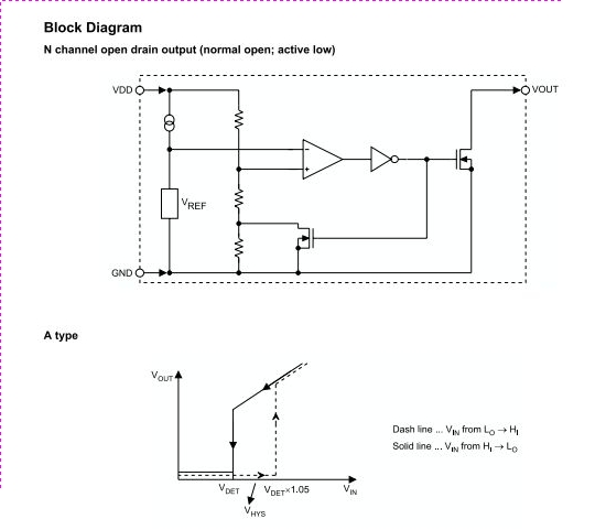
The HT70XX series comprises a collection of three-terminal low-power voltage detectors constructed using CMOS technology. Each voltage detector within the series is designed to detect a specific fixed voltage within the range of 2.2V to 7V. These detectors feature...
The SC9256 is a phase-locked loop (PLL) integrated circuit designed for digital tuning systems (DTS), featuring built-in 2 modulus prescalers. All functions are controlled through three serial bus lines. These integrated circuits are utilized to configure high-performance digital tuning...
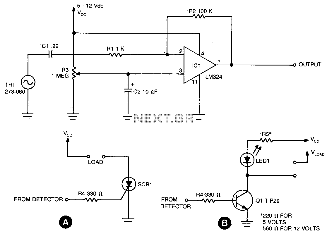
The sensing circuit is designed to detect both steady and fluctuating air flows. It utilizes a Radio Shack piezo buzzer (P/N 273-060) as its core component, along with an LM324 quad op-amp. The red wire from the piezo element...
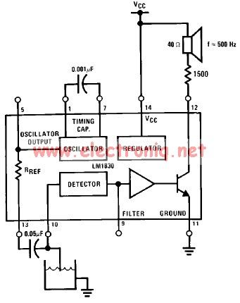
The LM1830 low-level detector can utilize an audio indication (speaker) or a visual indicator (LED - light-emitting diode) that activates when the level is too low. This low-level detector circuit generates a 500 Hz audio signal when the level...
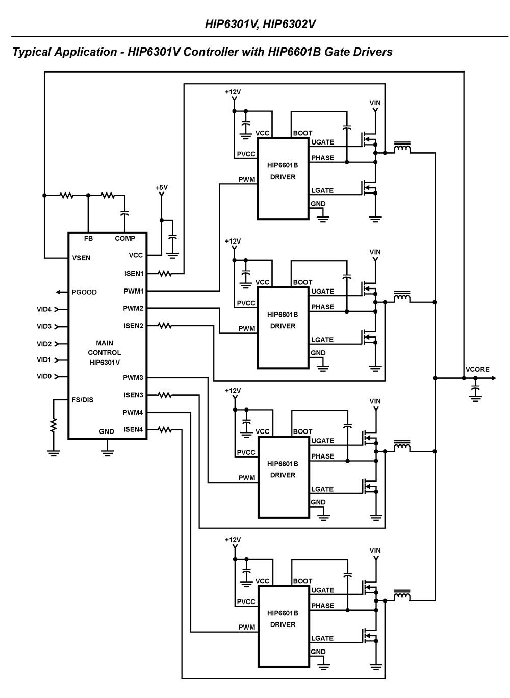
The HIP6301V and HIP6302V control the microprocessor core voltage regulation by driving up to four synchronous-rectified buck channels in parallel. The multiphase buck converter architecture employs interleaved timing to increase ripple frequency and minimize input and output ripple currents....