
phase shift oscillator

A phase-shift oscillator is a type of electronic oscillator that generates a sinusoidal output signal. It typically consists of an amplifier and a phase-shifting network that provides the necessary phase shift of 180 degrees, which is essential for the feedback loop to sustain oscillation. The phase-shifting network is usually composed of resistors and capacitors arranged in such a way that it introduces a total phase shift of 180 degrees at the desired frequency of oscillation.
The most common configuration includes three RC (resistor-capacitor) stages, each contributing a phase shift of 60 degrees, resulting in a total phase shift of 180 degrees when combined with the 180-degree phase shift from the inverting amplifier. This configuration allows for a stable oscillation frequency that can be determined by the values of the resistors and capacitors used in the phase-shifting network.
The output frequency of a phase-shift oscillator can be calculated using the formula:
\[ f = \frac{1}{2\pi R C \sqrt{6}} \]
where \( R \) is the resistance of the resistors in the network and \( C \) is the capacitance of the capacitors. The design of the oscillator must ensure that the gain of the amplifier is sufficient to compensate for the losses in the phase-shifting network, typically requiring a gain greater than three.
Phase-shift oscillators are widely used in various applications such as audio signal generation, tone generation, function generators, and as clock sources in digital circuits. Their simple design and ease of implementation make them a popular choice for low-frequency oscillation requirements.phase-shift oscillator. An oscillator in which a network having a phase shift o.. 🔗 External reference
Related Circuits
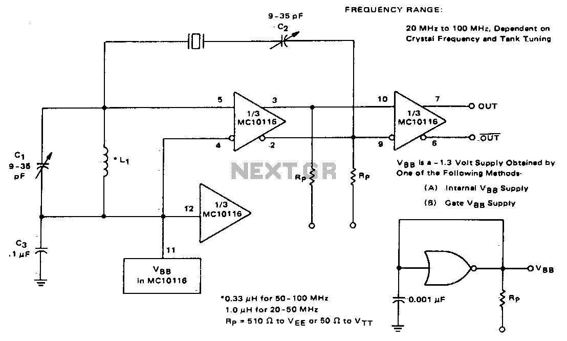
This circuit utilizes an adjustable resonant tank circuit that ensures operation at the desired crystal overtone. Capacitor C1 and inductor L1 form the resonant tank circuit, which can be adjusted to achieve a resonant frequency ranging from approximately 50...
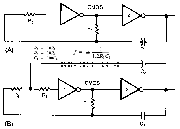
The common clock oscillator illustrated in Fig. 68-19A has two minor issues: it may not oscillate if the transition regions of its two gates differ. If it does oscillate, it might occasionally operate at a slightly lower frequency than...
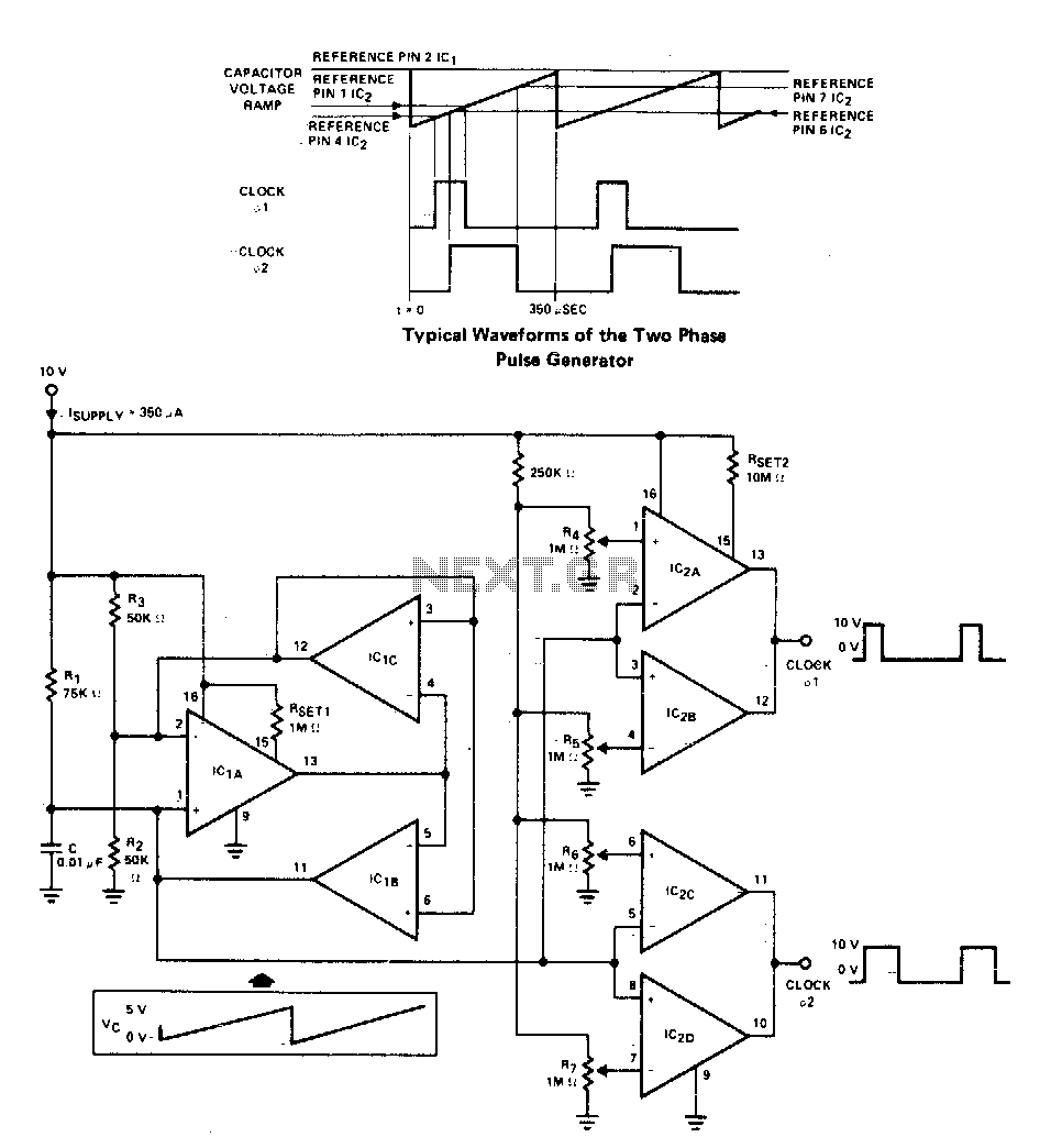
A two-phase clock generator utilizes two L161 integrated circuits to produce pulses with adjustable widths and phase relationships. Additionally, a ramp generator supplies input to two variable window comparators, which are configured using IC2A-IC2B and IC2C-IC2D, respectively. The two-phase clock...
If found myself in need of a 1 KHz signal source for an experiments. My function/sweep generator was needed as a pulse generator for the same experiment, so I went though my junk box, looking for circuits from long...
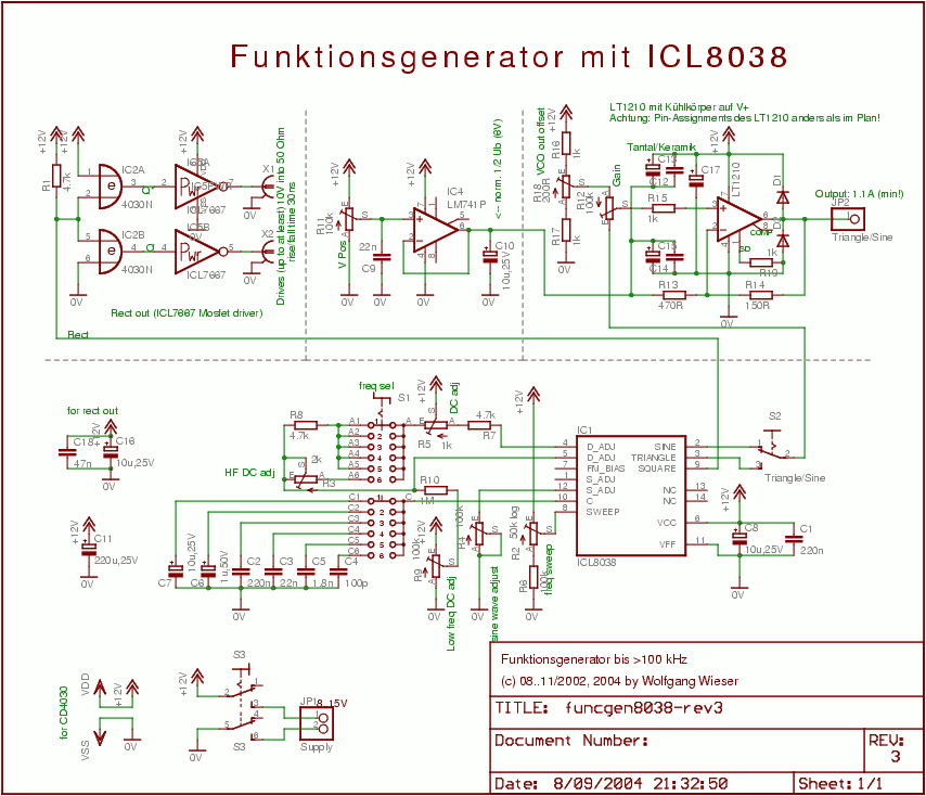
The circuit design is relatively straightforward. It features a Voltage Controlled Oscillator (VCO) utilizing the ICL8038 along with supplementary components, a sine and triangle output stage using the LT1210, and a CMOS-compatible output stage driven by the MOSFET driver...
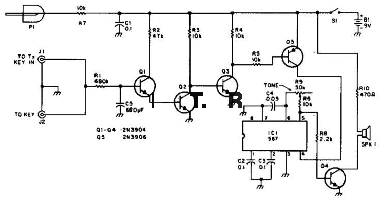
For use with low-power transmitters that require a positive keying voltage. The transistors Q1, Q2, and Q3 are configured as a switching amplifier. When the key is pressed, the collector of Q3 is pulled to ground, which activates Q5...