
pic frequency counter using 16f877a

The described frequency measurement circuit is designed to provide a real-time display of frequency values based on the input signal. The direct frequency measurement technique operates by counting the number of cycles of the input frequency over a defined time interval. The display output is directly proportional to the frequency being measured, which can lead to variations in the number of digits shown based on the input frequency level. For example, a higher frequency input may yield fewer displayed digits, while a lower frequency input could result in a more extensive numeric output.
To achieve a stable and consistent display of all significant digits regardless of frequency variations, the reciprocal counting technique can be implemented. This method involves calculating the reciprocal of the frequency, thereby allowing for a constant number of displayed digits. However, implementing reciprocal counting introduces complexity, as it requires the use of floating-point arithmetic or fixed-point routines. These routines are essential for managing the mathematical operations involved in calculating the reciprocal values accurately.
The hardware limitations of the circuit also play a crucial role in its design. The requirement for constant time routines is critical to maintain accurate frequency measurements. These routines ensure that the counting process is synchronized with the input signal, providing reliable and precise frequency readings. The challenge lies in the balance between the simplicity of the direct measurement method and the need for more complex algorithms to achieve a consistent display.
Overall, the circuit design must carefully consider the trade-offs between ease of implementation and the accuracy of frequency representation, especially when displaying all digits consistently across varying input frequencies.It uses the simpler method of direct frequency measurement which is easy to do but means that the number of digits displayed depends on the input frequency. If you want to display all digits all the time there is a technique called reciprocal counting- but this requires floating point (maybe fixed point) routines and would be difficult to implement with this hardware since it needsconstant time routinesto count accurately.
🔗 External reference
Related Circuits
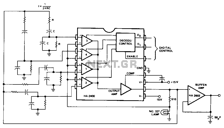
A Wien-bridge oscillator can be made variable by utilizing two frequency-determining components that are adjusted simultaneously with high tracking accuracy. However, high-quality tracking potentiometers or variable capacitors are often costly and challenging to procure. To circumvent the need for...
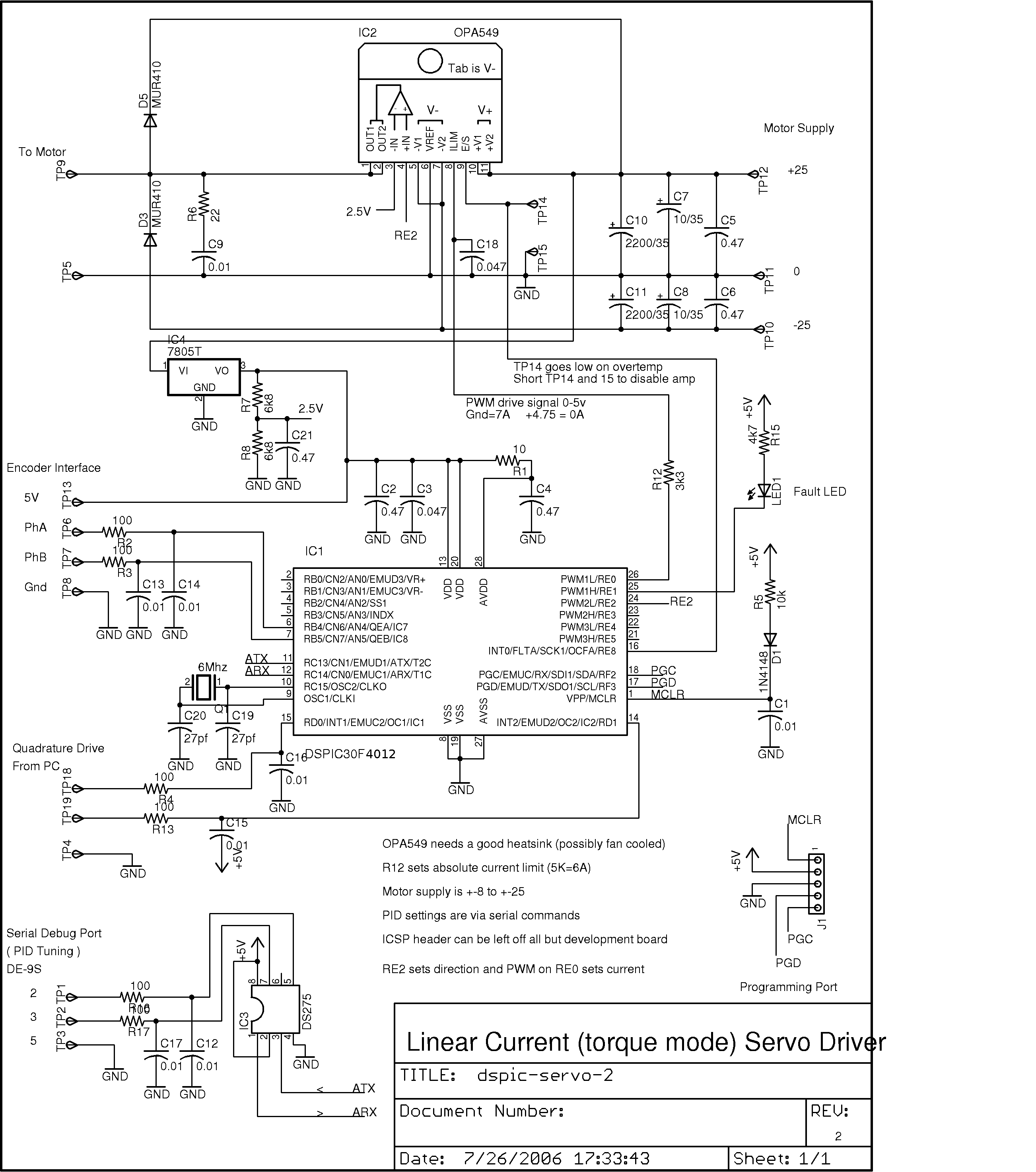
This project was developed as a cost-effective solution for driving small DC brushed motors as positioning servos for a desktop-sized CNC machine. The board interfaces with the PC through two pins of a parallel port, utilizing a quadrature drive...
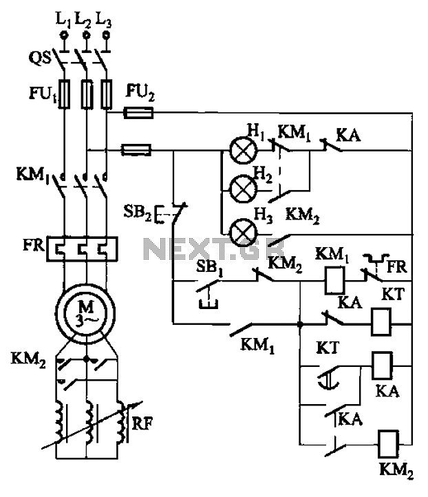
The circuit depicted in Figure 3-165 utilizes a time relay (KT) for controlling the start-up time. Indicator light Hi serves as the power indicator, H2 is designated for the start lights, and H3 functions as the running lights. The circuit...
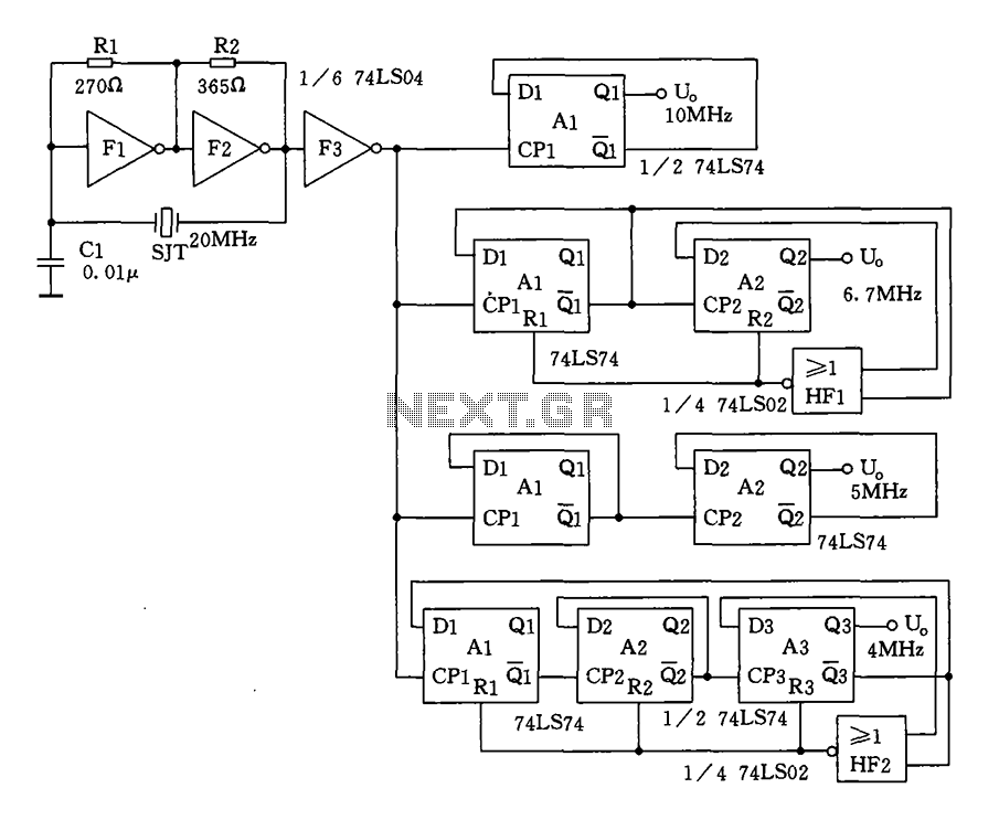
Crystal oscillator and frequency divider (74LS04) circuit diagram. The circuit diagram for a crystal oscillator combined with a frequency divider utilizing the 74LS04 integrated circuit is designed to generate a stable clock signal. The crystal oscillator component typically consists of...
The circuit was designed to create ten different frequency bands that can be processed by a single graphic equalizer to produce and maintain a predetermined frequency response. The described circuit is a graphic equalizer that utilizes a multi-band approach to...
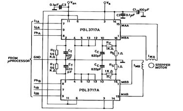
The diagram below illustrates a Two Phase Bipolar Stepper Motor Driver utilizing the PBL3717A. It depicts two PBL3717A integrated circuits (ICs) that control and drive two bipolar stepper motors. The Two Phase Bipolar Stepper Motor Driver circuit is designed to...