
Plasma DisplayCircuit using ICL7135 A/D Converter

The ICL7135 is a high-precision, low-power, integrating Analog to Digital Converter (ADC) that is well-suited for applications requiring accurate digital representations of analog signals. In the context of driving a plasma-type display, the circuit utilizes the ICL7135 to convert the analog voltage levels generated by the display's control signals into a digital format that can be processed and displayed.
The schematic typically includes the following key components: the ICL7135 ADC, power supply connections, input signal conditioning circuitry, and output interfaces for driving the plasma display. The input stage may consist of operational amplifiers configured to amplify and filter the analog signals to ensure they are within the acceptable range for the ADC.
The ICL7135 operates by integrating the input voltage over a specified time period, allowing it to provide high-resolution measurements. Its output is a binary-coded decimal (BCD) format, which can be easily interfaced with digital display drivers. The circuit may also incorporate additional elements such as reference voltage sources, timing control circuits, and multiplexers to manage multiple input signals.
In summary, the circuit diagram for driving a plasma-type display using the ICL7135 ADC exemplifies the device's versatility and capability to provide accurate digital conversions for various applications, particularly in display technologies.A circuit diagram for driving a plasma-type display using ICL7135 is shown in the following schematic. This application is one of the wide versatility variety of this integrating Analog to Digital Converter device
🔗 External reference
Related Circuits
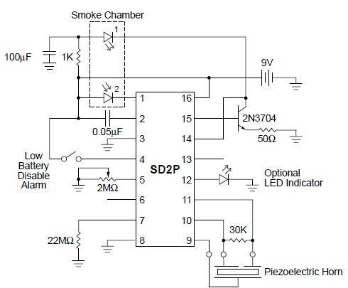
This smoke detector circuit diagram is based on the SD2 CMOS Photo-Electric Smoke Detector Integrated Circuit manufactured by Supertex Inc. It includes almost all the necessary components to build a simple and highly efficient smoke detector project. The LED...
The circuit described operates similarly to a previous design but utilizes a laser pointer to activate the relay instead of a push button. An IR photo transistor (model Q1, Radio Shack 276-145A or equivalent) is connected to the set...
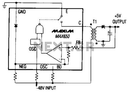
The Max650 switching regulator generates a regulated 5 V output from large negative voltages, such as the -48 V commonly found on telephone lines. This power supply requires several external components, including a transformer, and is capable of delivering...
The 2N3819 is an n-channel JFET specifically designed for RF and mixer applications, offering very low noise, minimal distortion, and excellent high-frequency gain. Creating a PCB can be accomplished in a few straightforward steps. Begin by using PCB design...
The purpose of this application note is to present an example circuit illustrating the operation of the XR-T5683 device at a data rate of 10.1 Mbps. This note includes the results of measurements taken on the XR-T5683 at this...
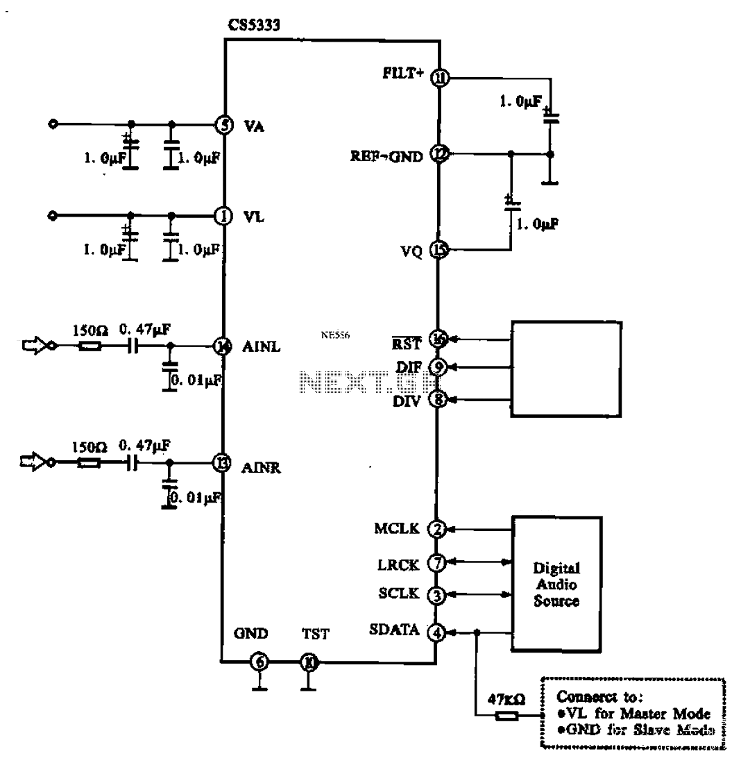
Audio A/D converter circuit configuration using the CS5333 chip, which is a high-performance 24-bit, 96 kHz stereo A/D converter commonly used in digital products. This circuit converts one or more audio signals into a digital signal for processing and...