
Portable Nicad Charger

The portable charger circuit is structured to facilitate the charging of NiCad batteries while ensuring safety and functionality. The main components include an integrated circuit (IC1) for voltage regulation, a transistor (T1) for conducting current based on polarity detection, and a CMOS timer (IC2) for controlling the charging duration. The circuit begins operation upon connecting to a car battery, where the LED indicator (D2) confirms correct polarity.
The resistor R8 plays a critical role in biasing the base of T1, ensuring that even a minimal voltage from a discharged NiCad battery can activate T1, illuminating D2 as a visual confirmation. The start switch (S1) initiates the charging process, but only under the condition that the battery is connected with the correct polarity. The transistor T1, when activated, allows a low collector voltage, which subsequently triggers IC2. The monostable operation of IC2 ensures that the charging process is timed correctly, with the output pulse duration determined by the values of P1 and R4.
Charging begins when T2 is activated, energizing relay Rel, which connects the charging circuit to the NiCad battery through R5 and D6. The charging current is monitored and controlled by resistor R, which is crucial for preventing overcurrent situations. The charging indicator (D4) provides feedback to the user, signaling that charging is in progress.
Capacitor C4 is charged during the process, and its charging time is influenced by the potentiometer P1 and resistor R4. The design allows the user to adjust the charging duration, which is essential for different battery capacities. The recommended range of 26 to 33 minutes is optimal for most NiCad batteries, ensuring efficient charging without damage.
The reset switch (S2) offers an additional layer of control, allowing users to interrupt the charging process if necessary. Proper selection of resistor R is vital, as it must handle the power dissipation calculated from the charging current. The overall design emphasizes safety and efficiency, ensuring that users can charge their NiCad batteries effectively while minimizing the risk of damage from prolonged charging. Adhering to the recommended charging times and using high-quality components will enhance the reliability and longevity of both the charger and the batteries. The portable charger is intended primarily to give model enthusiasts the opportunity of charging their Nicad batteri es from a car battery out in the open. The supply voltage for the circuit is regulated by IC1. When the circuit is connected to the car battery, D2 lights only if the Nicad to be charged has been connected with correct polarity. For that purpose, the + terminal of the Nicad battery is connected to the base of T1 via R8. Because even a discharged battery provides some voltage, T1 is switched on and D2 lights. Only if the polarity is correct will the pressing of the start switch, SI, have any effect. If so, the collector voltage of T1 is virtually zero so that monostable IC2 is triggered by SI. The output, pin 3, of this CMOS timer then becomes high, T2 is switched on and relay Rel is energized.
Charging of the Nicad battery, via R5 and D6, then begins and charging indicator D4 lights. During the charging, C4 is charged slowly via PI and R4. The value of these components determines the mono time of IC2 and thus the charging period of the Nicad battery. With values as shown in the diagram, that period can be set with PI to between 26 and 33 min. Notice that this time is affected by the leakage current of C4; use a good-quality capacitor here. The charging can be interrupted with reset switch S2. The charging current through the Nicad battery is determined by the value of R, which can be calculated: Ic is the charging current, which is here because the chosen charging period is twice the nominal value of the capacity of the Nicad battery.
Resistor R must be able to dissipate a power of 1/ R W. Finally, make sure that the Nicad battery is suitable for fast charging; never charge for longer than half an hour!
Related Circuits
Switching to alternative power sources can lead to savings on electricity bills. The photovoltaic module or solar panel discussed here has a power output of 5 watts. Under full sunlight conditions, the solar panel generates 16.5V and can provide...
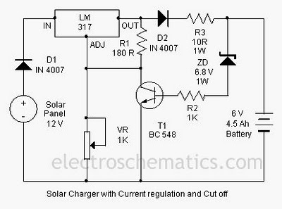
A solar charger circuit is designed to charge lead-acid batteries or nickel-cadmium (Ni-Cd) batteries using solar power. This circuit captures solar energy to charge a 6-volt, 4.5 Ah battery for various applications. It features voltage and current regulation along...
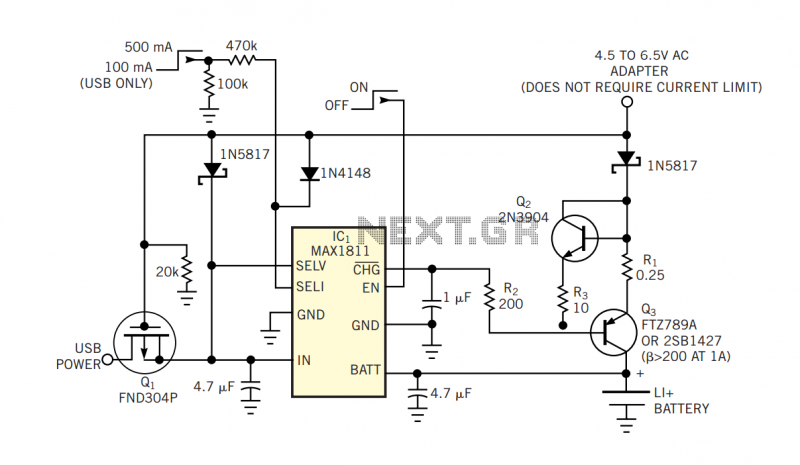
The popular USB interface can charge a portable device while transferring data. But for high-capacity batteries, the 500-mA output current of USB hosts and powered hubs greatly extends the charging time. Thus, a system that accepts charging power from...
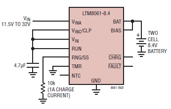
A simple and efficient lithium battery charger and monitoring system can be designed using the LTM8061 integrated circuit from Linear Technology. The LTM8061 is a high-efficiency 32V, 2A module standalone lithium battery charger optimized for one- and two-cell packs,...
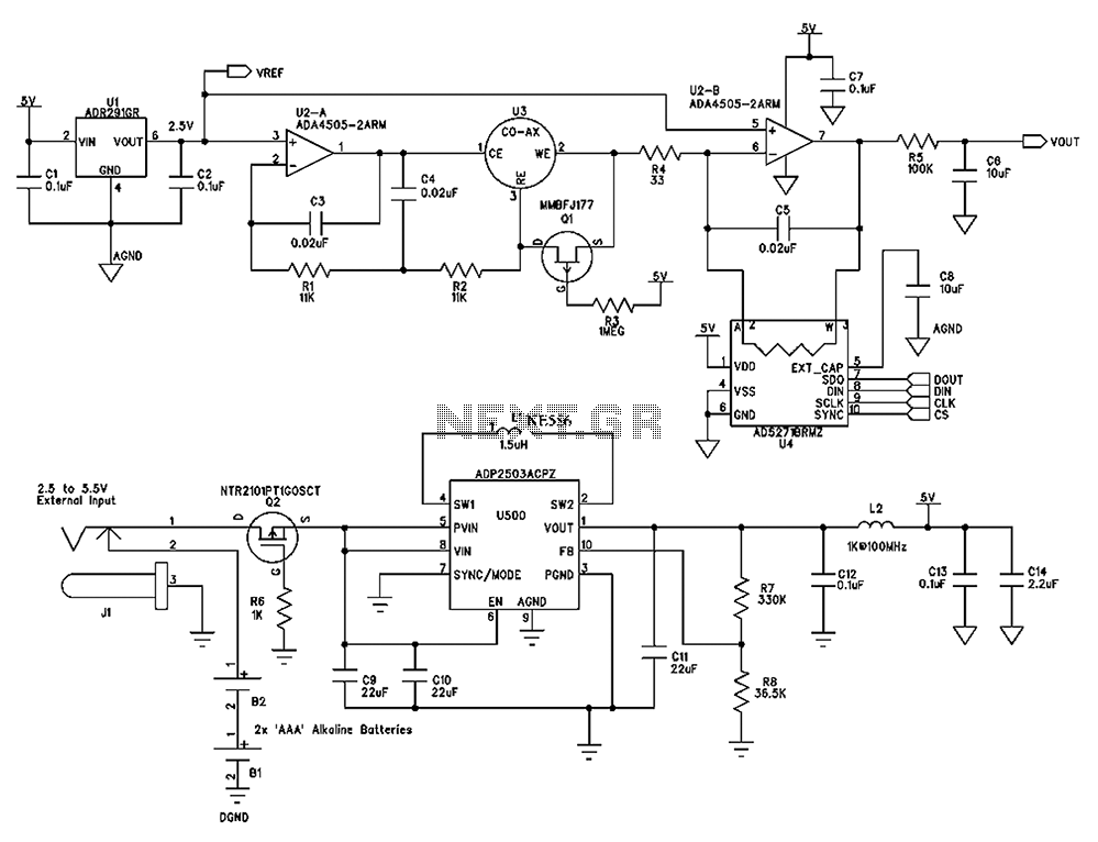
The circuit diagram presented below illustrates a portable gas detector. This device primarily utilizes electrochemical sensors and features dual-channel micro-power amplifiers, specifically the ADA4505-2. These amplifiers are configured in both a constant potential (U2-A) and a transconductance configuration (U2-B)....
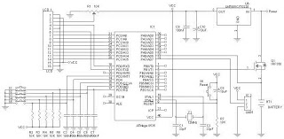
A battery charger can be understood as a device designed to replenish the charge in a battery. An effective charger circuit should provide the necessary resources for efficient and safe battery charging. The AVR-Based Battery Charger utilizes the ATMega...