
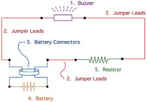
Power Buzzer

The described circuit is designed to activate a buzzer when a pushbutton is pressed, providing an audible alert in specific situations, such as when someone is at the bottom of the stairs or in a kitchen area. The TDA2030 integrated circuit serves as the primary amplifier in this configuration, capable of driving the buzzer with sufficient power while ensuring stability and reliability due to its thermal protection features.
The resistors R1 and R2 are configured as a voltage divider, ensuring that the positive input of the op-amp receives a stable reference voltage, which is critical for proper operation and oscillation. Resistor R3 is essential for creating positive feedback, which is necessary for the oscillation process. The values of R1, R2, and R3 must be carefully selected to achieve the desired gain and feedback characteristics.
The frequency of the oscillation, which directly affects the sound produced by the buzzer, is determined by the values of capacitor C2, resistor R4, and the adjustable trimmer potentiometer P12. The trimmer allows for fine-tuning of the frequency, enabling customization of the buzzer's sound output according to user preference.
In summary, the circuit effectively combines a pushbutton switch and a buzzer, utilizing a TDA2030 integrated circuit to generate an audible alert. The design emphasizes reliability and customization, making it suitable for various applications where alert signals are necessary. Proper component selection and configuration are crucial for achieving optimal performance in this buzzer activation circuit.A powerful buzzer in the room, combined with a pushbutton at the bottom of the stairs or in the kitchen, could be very handy in such situations. The heart of this circuit is formed by IC1, a TDA2030. This IC has built-in thermal protection, so it`s not likely to quickly give up the ghost. R1 and R2 apply a voltage equal to half the supply voltage to the plus input of the opamp. R3 provides positive feedback. Finally, the combination of C2, R4 and trimmer P12 determines the oscillation frequency of the circuit. Power Buzzer Circuit Diagram. 🔗 External reference
Related Circuits

This document presents a basic electronics project focused on creating a regulated power supply. A regulated power supply is essential for various electronic circuits, as it provides a constant voltage necessary for their operation. Understanding how to construct a...

This is a stereo amplifier circuit that delivers high output power and excellent sound quality. The amplifier circuit features a very high gain output stage, which can result in signal noise deterioration. It is capable of providing an output...
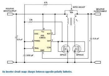
To transfer charge in either direction between unevenly loaded positive and negative battery buses, an inverting DC transformer is required. One implementation is the symmetrical flyback converter, which can produce a negative output from a positive supply or a...
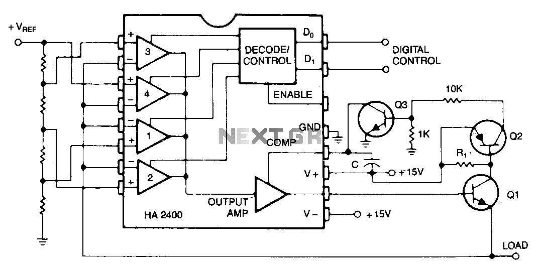
Many systems require one or more relatively low-current voltage sources that can be programmed to a few predetermined levels. The circuit presented generates positive output levels but can be modified for negative or bipolar outputs. Q1 serves as the...
The drive circuit is a basic drive recently designed to accommodate a 27mm passive piezoelectric buzzer, aiming for a sound output exceeding 100dB while minimizing power consumption. Due to constraints related to product cost and structural size, the circuit...
A voltage regulator is connected across the solar cell to prevent damage to the storage battery due to overcharging. A series diode prevents the array from discharging the battery during hours of darkness. The regulator does not draw power...