
Power Control Unit

The power control unit circuit diagram illustrates the fundamental components and their interconnections, providing a clear overview of the functionality and operation of the system. The main relay, positioned on the left side of the diagram, acts as a pivotal element in the circuit, serving to control the flow of power through the system. It is activated by the key switch, which functions as an input device allowing the user to initiate or terminate power delivery.
In a typical configuration, when the key switch is turned to the 'on' position, it completes the circuit, allowing current to flow to the relay coil. This energizes the relay, causing it to close its contacts and connect the power source to the load, thereby supplying power to the intended devices or circuits. The relay's contacts are rated for the specific voltage and current levels of the application, ensuring safe and efficient operation.
In addition to the main relay and key switch, the circuit may include additional protective elements such as fuses or circuit breakers to prevent overload conditions. These components are critical for safeguarding the entire system from potential damage due to excessive current or short circuits.
Furthermore, the circuit diagram may also depict various indicators, such as LED status lights, which provide visual feedback on the operational state of the power control unit. These indicators enhance user interaction by signaling whether the system is powered on or off, and they can be integrated in parallel with the relay contacts.
Overall, the power control unit circuit diagram serves as an essential reference for understanding the design, operation, and safety features of the system, facilitating troubleshooting and maintenance activities.This a shows the overall circuit diagram of the power control unit. On the left, there is a main relais controlled by the key switch and the . 🔗 External reference
Related Circuits
The LM317 is an adjustable, positive 3-terminal voltage regulator capable of supplying 100 mA (for RA87U control) or 1.5 A (for Order Code UF27E and N61CA) across an output voltage range of 1.2 V to 37 V. These voltage...
The controller for a Hybrid Power Plant (HPP) block diagram consists of 440 Wp photovoltaic modules, a 1 kW wind turbine, and a 5 kW diesel engine as a backup. The HPP functions as a centralized PV and wind...
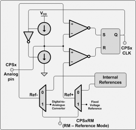
There are numerous applications for this hardware, including touch pads, proximity sensors, capacitive sensor readouts, high-precision capacitance measurements, ultra-small capacitance change detection, soil moisture sensing, and skin moisture measurement, among others. However, after searching for examples, it was surprising...
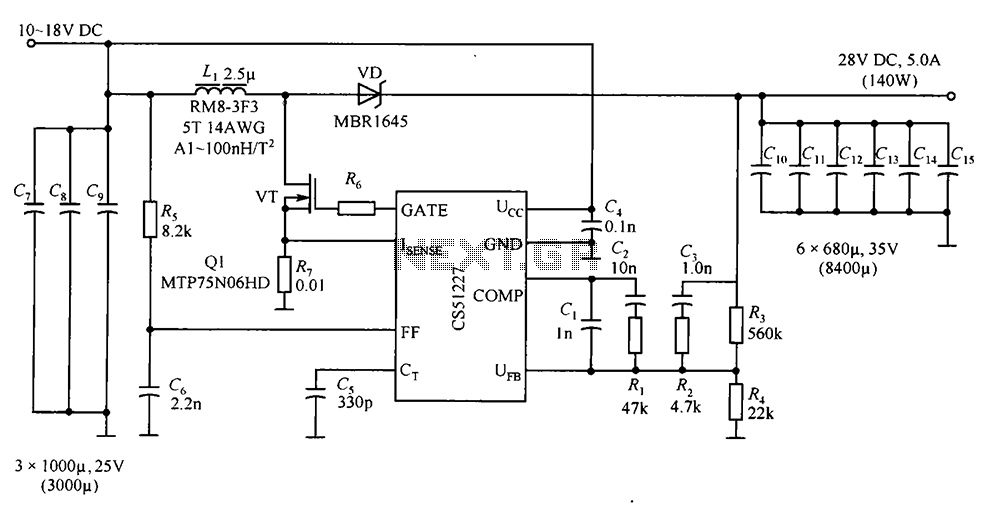
CS51227 is a voltage-type PWM controller that delivers an output of 28V with a maximum current of 5A. The switching frequency is 1.0 MHz, with a starting voltage of 4.7V and a starting current of 75A. The input voltage...
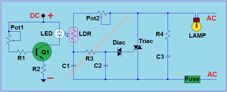
This is another AC light dimmer, with the primary distinction being that its control circuit is isolated from the AC line, making it much safer to use. The circuit can operate on both 120V and 220V AC lines. Note:...
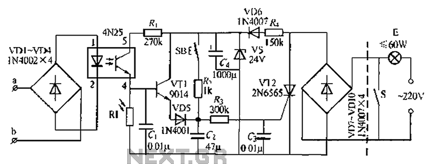
An automatic light system is integrated with a telephone block system. When the phone rings, the owner is prompted to pick up the handset or pull a lever, causing the lamp to light up. If there is no contact...