
Power FET Lamp Flasher

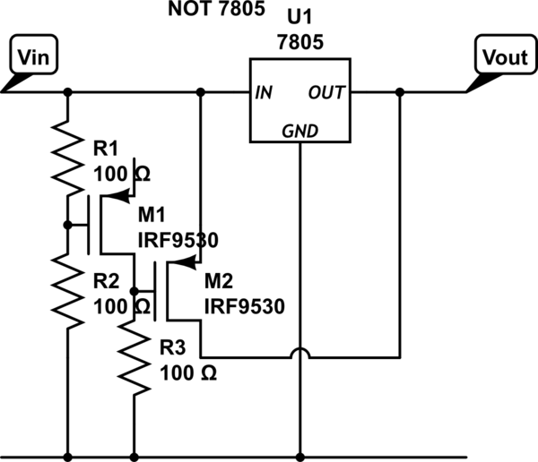
The proposed lamp flasher circuit utilizes two power Field-Effect Transistors (FETs) to control the alternation of a lamp's illumination. This design offers several advantages over traditional bipolar transistor circuits, including higher efficiency and faster switching times.
In this configuration, the two power FETs are arranged in a complementary manner, allowing one FET to conduct while the other is off, and vice versa. This creates a pulsing effect that can be adjusted for various flashing rates by incorporating a timing circuit, typically based on a resistor-capacitor (RC) network or a microcontroller.
The circuit begins with a control signal that triggers the first FET, allowing current to flow through the lamp, which illuminates. Once the control signal is removed, the first FET turns off, and the second FET is activated, completing the circuit and allowing the lamp to flash alternately. This switching can be controlled through various means, such as a timer IC, a 555 timer, or a microcontroller, which can provide precise timing adjustments.
The use of power FETs in this application enhances the thermal performance of the circuit, as they typically have lower on-resistance compared to bipolar transistors, resulting in reduced power loss and heat generation during operation. Additionally, the FETs can be driven directly by low-voltage logic signals, simplifying the control circuitry.
To ensure reliable operation, it is essential to include protection components such as diodes to prevent back EMF from inductive loads, which can damage the FETs. Proper heat sinking may also be required to dissipate heat generated during operation, particularly at higher current levels.
Overall, this lamp flasher circuit design with power FETs presents an efficient and reliable alternative to traditional bipolar transistor-based designs, suitable for various applications in lighting control systems.As an alternative to bipolar transistor, a lamp flasher can be built by using two power FETs. Like other flasher circuit, this circuit alternately switch the.. 🔗 External reference
Related Circuits
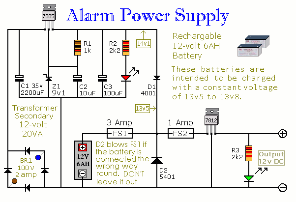
This Power Supply is suitable for the Modular Burglar Alarm. However, it has other applications. It is designed to provide an output of 12-volts, with a current of up to 1-amp. In the event of mains failure, the back-up...

The LM3434 adaptive constant on-time DC/DC buck (step-down) constant current controller can be used to design a simple high-power LED driver application. The LM3434 provides a constant current for illuminating high-power LEDs. The output configuration allows the anodes of...
This chapter contains circuit diagrams for various power supplies designed for pulsed solid-state lasers. These include units suitable for driving the widely used Hughes ruby and YAG rangefinder laser assemblies, one utilizing the flash from a disposable pocket camera,...

Illuminate your tabletop with this stylish White LED Lamp. It is powered through a USB port, making it perfect for taking notes while browsing the internet. The USB port can provide a convenient power source. The White LED Lamp is...

A simple 16-volt switching power supply circuit can be constructed using the provided diagram, which is based on the MAX668 constant-frequency, pulse-width modulating (PWM), current-mode DC-DC controller. This integrated circuit is designed for a wide range of DC-DC conversion...
Supply it with a Li-Ion cell, which has a voltage range of 2.7 to 4.2V. The complexity of a buck/boost converter is not desired. While it is possible to regulate the voltage down to anything below 2.5V, it would...