
Power from PC's RS-232 circuit

Modern PCs typically have a 9-pin port instead of this older 25-pin port. To use this circuit with such a PC, there are two options: use a 9 to 25 pin adapter or modify the circuit for a 9-pin port. More current can be obtained from the circuit by omitting the resistors (R1, R2, R3) and replacing them with a short piece of wire. The 78L05 regulator consumes 3-4 mA of current continuously and requires at least a 2V voltage drop; thus, finding a similar regulator that consumes less current and has a lower voltage drop would yield more current for the circuit. Some small signal input circuits have been observed to take positive and negative supplies for simple operational amplifier circuits just by using DTR and RTS lines. By driving one of these lines high (1) and the other low (0) using appropriate software routines, positive and negative voltages can be obtained from those pins.
The amount of power that can be drawn from a serial port depends on the circuit technology used in the serial port. B&B Electronics Connection Newsletter number 2 contains a useful article titled "Tips For Using Port Powered Converters," which discusses the potential power output from various serial ports. The following data is extracted from that article:
Type of Driver | State of Line | Voltage at No Load | Voltage/Current per Driver (Max) | Power Available from 3 Driver Outputs
------------------|---------------|---------------------|-----------------------------------|--------------------------------------
1488 | Positive | +9..11V | +5V @ 6.5 mA | 98 mW
1488 | Negative | -9..11V | -5V @ 6.5 mA | 78 mW *
MAX232 | Positive | +7.5V..8V | +5V @ 5 mA | 75 mW
MAX232 | Negative | -7.5..8V | -5V @ 3.5 mA | 42 mW *
EIA-562 | Positive | +3.7..5V | +4.5V @ 1.5 mA | None
EIA-562 | Negative | -3.7..5V | -4.5V @ 1.5 mA | None
Note: The power ratings are what can be obtained using the methods described by B&B Electronics in their circuits. The values marked with an asterisk (*) represent the power available after converting the negative power to positive +5V with additional electronics connected to the serial port.
Additionally, another table illustrates the power available from different computers via the RS-232 port RTS line and how the load affects the available voltage. This information has been collected from RS-232 powering articles posted to the sci.electronics.design newsgroup. Although these results have not been verified, they seem to align with similar values found during RS-232 experiments and should be applicable to other RS-232 port lines in PCs (TXD and DTR).
Simple circuits that do not draw much power (less than 2 mA) can derive their power from a single serial port line (DTR, RTS, or TD). An example of this approach is a Serial Port A/D converter circuit that utilizes power from the DTR line, regulating it to +5V with a 1 kΩ resistor and a 5.1V zener diode.The following circuit is an example how to get power from RS-232 serial port. It gives regulated +5V power for logic circuits and also unregulated positive and negative power supplies for RS-232 transmitting circuit. The circuit gives only few milliampres power output because the power available from serial port is limited (and resistors R1, R2 and R3 limit current more).
Modern PCs have typically 9 pin port instead of this older 25 pin port. If you want to use this circuit with such PC you have two options: use a 9 to 25 pin adapter or modify the circuit to 9 pin port. You can get a little bit more current from the circuit if you leave out the resistors (R1, Rs, R3) and replace them with short piece of wire.
78L05 regulator takes 3-4 mA current all the time and needs at least 2V voltage drop, so if you can find a similar regulator which takes less current and has lower voltage drop, you get more current for your circuit. Some small circuits signal input circuit I have seen have taken positive and negative supplies for simple operational amplifier circuit just by using DTR and RTS lines.
Just by driving one of them to 1 and other to 0 using suitable software routine, there are available positive and negative voltages from those pins. How much you can really draw from a serial port depends on the circuit technology used in the serial port.
B&B Electronics Connection Newsletter number 2 has a good article "Tips For Using Port Powered Converters" about how much you can really get power from different serial ports. The following data is extracted from the article text: Type of State of Voltage Voltage/current Power available from Driver Line at no load per driver (max) 3 driver outputs 1488 positive +9..11V +5V @ 6.5 mA 98 mW 1488 negative -9..11V -5V @ 6.5 mA 78 mW * MAX232 positive +7.5V..8V +5V @ 5 mA 75 mW MAX232 negative -7.5..8V -5V @ 3.5 mA 42 mW * EIA-562 positive +3.7..5V +4.5V @ 1.5 mA none EIA-562 negative -3.7..5V -4.5V @ 1.5 mA none NOTE: The power ratings are what can be obtained used the methods B&B Electronics uses in their circuits.
The values marked with * are the power available after the negative power is converted to positive +5V with extra electronics in the circuit connected to serial port. Here is another table how much power is available from different computers form RS-232 port RTS line and how the load affect the available voltage.
Information is collected from the RS-232 powering articles posted to sci.electronics.design newsgroup. I have not verified those results but those seems to be quite similar values what I have found in my RS-232 experiments and should be applicable to also to other RS-232 port lines in PCs (TXD and DTR).
Some simple circuit which does not take much power (less than 2 mA) can take their power simply from one serial port line (DRT, RTS or TD). I have used this approach at my Serial Port A/D-converter circuit, where is have taken power from DTR line and regulated it to +5V with 1 kohm resistor and 5.1V zener diode.
🔗 External reference
Related Circuits
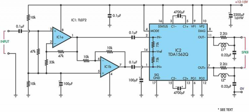
This circuit is based on a Philips class-H audio amplifier integrated circuit (IC) and can deliver 36W RMS or 70W music power, all from a 13.8V supply. The Mighty Midget Amplifier is capable of providing approximately 36W RMS continuous...
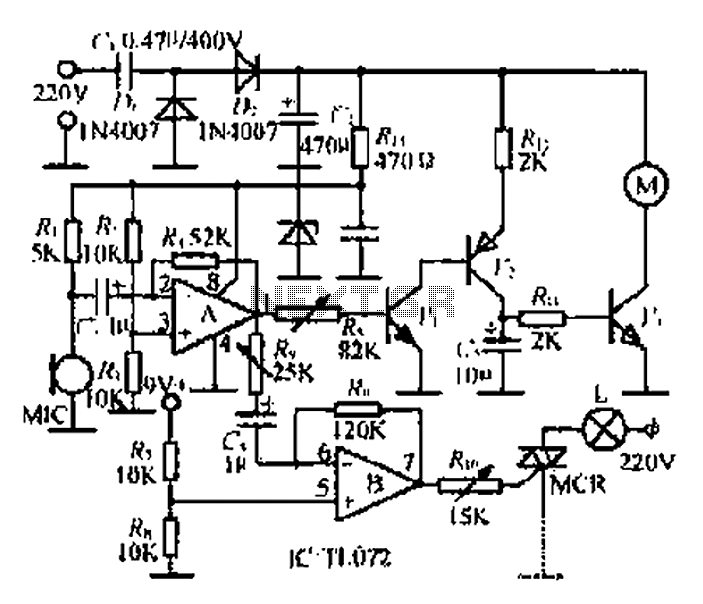
A microphone (MIC) is used to capture sound, which is then converted into a voltage signal. An operational amplifier (op-amp A) acts as a buffer; one output is directed to a motor drive circuit to control the motor's rotation...
A device that conducts electric current and converts electrical energy into another form. Power consumed by a device or circuit while performing its function can be represented by a resistor and capacitor. The capacitor in the load circuit represents...
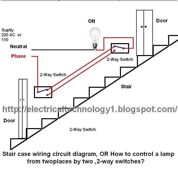
The circuit is complete, and the bulb is ON. To turn OFF the bulb from the upper switch at the top of the stairs, simply turn OFF the switch, which will break the circuit and turn the bulb OFF....
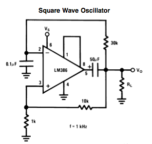
Here is a small LM386-based square-wave oscillator constructed from the following schematic. A 50k potentiometer was used in place of a 30k resistor, which functions as a pitch controller. The audio provided consists of track recordings made in Ableton...
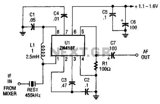
The ZN416E can be configured as a simple 455-kHz IF amplifier. In this case, the circuit's center frequency and bandwidth are set by RES1, which is a Murata CSB455E ceramic resonator. The ZN416E is a versatile integrated circuit designed specifically...