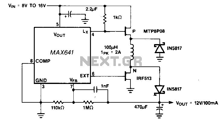
Step-up-down-dc-dc-converter

Positive output step-up and step-down converters have a common limitation in that neither can handle input voltages that are both greater than or less than the output. For example, when converting a 12-V sealed lead-acid battery to a regulated +12 V output, the battery voltage might vary from a high of 15 V down to 10 V. By using a MAX641 to drive separate P- and N-channel MOSFETs, both ends of the inductor are switched to allow non-inverting buck/boost operation. A second advantage of the circuit over most boost-only designs is that the output goes to 0 V when shutdown is activated. Inefficiency is a drawback because two MOSFETs and two diodes increase the losses in the charge and discharge path of the inductor. The circuit delivers +12 V at 100 mA at 70 percent efficiency with an 8-V input.
The described circuit utilizes a configuration that enables both step-up (boost) and step-down (buck) voltage conversion, addressing the limitations typically associated with conventional converters. The circuit is designed to manage input voltage fluctuations, particularly when converting from a variable voltage source such as a 12-V sealed lead-acid battery. The battery voltage can range from 10 V to 15 V, necessitating a versatile solution that can maintain a constant output voltage of +12 V despite these variations.
At the heart of the circuit is the MAX641, which serves as a controller to drive both P-channel and N-channel MOSFETs. This dual-MOSFET configuration allows for efficient switching of the inductor, facilitating non-inverting buck/boost operation. In this mode, the inductor's current can be controlled to either step up or step down the voltage as required by the load conditions.
A notable feature of this circuit is its ability to bring the output voltage down to 0 V upon shutdown. This is advantageous in applications where power conservation is critical, as it prevents any residual output voltage that could affect downstream components or systems.
However, the design does have some inefficiencies. The inclusion of two MOSFETs and two diodes introduces additional losses in both the charge and discharge paths of the inductor. These losses can reduce overall efficiency, which is measured at approximately 70 percent when delivering +12 V at 100 mA from an 8-V input. This efficiency metric highlights the trade-off between the flexibility of the buck/boost operation and the inherent losses associated with the circuit's architecture.
Overall, this circuit represents a robust solution for applications requiring a regulated output voltage from a variable input source, albeit with considerations for efficiency and component selection in the design process.Positive output step-up and step-down de-de converters have a common limitation in that neither can handle input voltages that are both greater than or less than the output. For example, when converting a 12-V sealed lead/acid battery to a regulated +12 V output, the battery voltage might vary from a high of 15 V down to 10 V.
By using a MAX641 to drive separate P-and N-cbannel MOSFETs, both ends of the inductor are switched to allow noninverting buck/boost operation. A second advantage of the circuit over most boostonly designs is that the output goes to 0 V when shutdown is activated. Inefficiency is a drawback because two MOSFETs and two diodes increase the losses in the charge and discharge path of the inductor.
The circuit delivers +12 V at 100 mA at 70 percent efficiency with an 8-V input.