
Power Supply Failure Alarm

The power supply failure alarm circuit is designed to monitor the status of a power supply and provide an alert in the event of a failure. This circuit is particularly advantageous as it eliminates the need for an additional power source, which is a common requirement in traditional alarm systems.
The core of the circuit typically includes a voltage comparator, which continuously monitors the output voltage of the power supply. If the voltage drops below a predetermined threshold, indicating a failure, the comparator triggers an alarm signal. This alarm signal can be visualized through an LED indicator or can activate a relay to control external devices, such as a warning siren or a notification system.
Key components of the circuit may include resistors, capacitors, and diodes, which are used to set the voltage reference levels and filter noise from the power supply. The design may also incorporate a microcontroller for more advanced features, such as logging failure events or sending alerts via communication interfaces.
The schematic layout should ensure that the monitoring section is isolated from the load section to prevent any interference from the load's operational noise. Proper grounding and decoupling techniques must be employed to enhance the reliability of the circuit.
Overall, this power supply failure alarm circuit is a critical component in many electronic systems, providing essential monitoring capabilities without the added complexity of an independent power supply.This is the special circuit design of power supply failure alarm. The vast majority of the power supply failure alarm / indicator circuits require a independent power supply for themselves. However the alarm circuit introduced right here re.. 🔗 External reference
Related Circuits
These photos were made in the years 1956 and 1957. On photo nr. 3, on the right, at the bottom, is the GMD. The work that was done at the objekt was of course top secret. It was strictly...
This is an efficient four-stage stabilized power supply unit designed for testing electronic circuits. It delivers well-regulated and stabilized outputs, which are crucial for achieving accurate results in most electronic applications. The circuit features an audio-visual indication system that...
The NE568A (NE568AD, NE568AN, SA568AD, SA568AN) is a monolithic phase-locked loop (PLL) that operates from 1Hz to frequencies exceeding 150MHz. It features an extended supply voltage range and a lower temperature coefficient of the VCO center frequency compared to...
A micro power solar engine has been a goal since the introduction to BEAM Robotics. It is believed that if one did not exist previously, there is now an available design. The presented circuit closely resembles one found on...
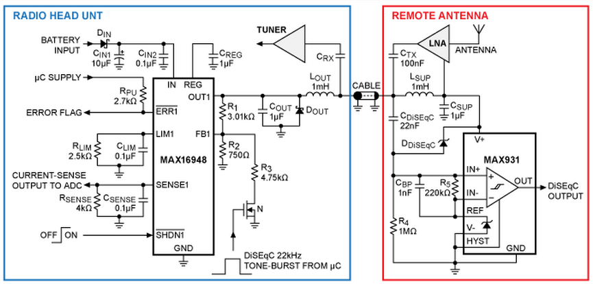
A design for a phantom antenna power-supply system compatible with the Digital Satellite Equipment Control (DiSEqC) communication standard, utilizing the MAX16948 automotive dual, high-voltage LDO/switch. The application circuit provides a remote antenna power supply and enables one-way communication from...
On average, how often do you need to call family members each day to inform them that dinner is ready or that it's time to leave? Typically, the person being called is in a different room, such as a...