
power supply Transistor current limiter microcontroller controlled

To design a circuit that utilizes Rsense to control the conduction of Q2 based on a sensed voltage, a high-side current sensing configuration is recommended. In this setup, Rsense is placed in the high side of the load, allowing for the measurement of current flowing through the load without interrupting the circuit. When the voltage across Rsense exceeds the threshold of 0.65V, Q2 is triggered to conduct, which can be accomplished by connecting Q2 to a comparator circuit.
The comparator can take the voltage across Rsense as one input and a reference voltage defined by the microcontroller as the other input. This reference voltage can be set to any desired limit, allowing for flexibility in current control. The output of the comparator can then be used to drive the gate of Q2, turning it on when the sensed voltage exceeds the reference voltage.
Rbias plays a critical role in this configuration, as it can be used to establish a desired current limit by creating a voltage divider with Rsense. By adjusting Rbias, the threshold voltage at which Q2 conducts can be fine-tuned. If Rbias is not implemented, the circuit may not effectively limit the current to the desired level, resulting in potential overcurrent conditions.
To initiate the limiting process, the microcontroller can periodically sample the voltage across Rsense. When the sensed current is sufficient to trigger the comparator, the microcontroller can take appropriate actions, such as reducing the duty cycle of a PWM signal or activating a control signal to limit the load current.
In summary, a well-designed circuit using Rsense and a comparator can provide an effective means of controlling current through a load. The combination of Rsense, Rbias, and a microcontroller allows for dynamic adjustment of the current limit without the need for a digital potentiometer, ensuring both flexibility and precision in current control applications.Rsense would cause Q2 to conduct if at a threshold (0. 65V assumably) and Rbias will determine how much it will be limited, however that is unclear to me, especially if Rsense will be somewhere highside and just turning on Q2 with my uC seems to not do anything (in simulation at least) How would I come up with the formulas for a variable limit that I can control I would rather not have to use a digital potentiometer in place of R2, if I can somehow have sense voltage compared with a comparator with a voltage my uC defines, that`d be great! But how could I start the limiting What do I "turn on" when the sense resistor shows enough current Does Rbias have to be there to limit it to a certain level, and I`ll end up having to use a digipot anyway
🔗 External reference
Related Circuits
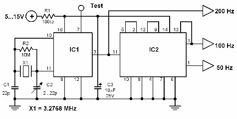
This circuit generates a 50 Hz timebase signal that is independent of the power line frequency. It is designed to provide the 50 Hz signal for electronic circuits that operate specifically with this clock frequency, primarily for circuits and...
This circuit is designed to serve as a programmable LED display for various applications. It features an 8 x 32 LED dot matrix interfaced with a Xino (or Arduino). In addition to the display, the circuit includes two buttons...
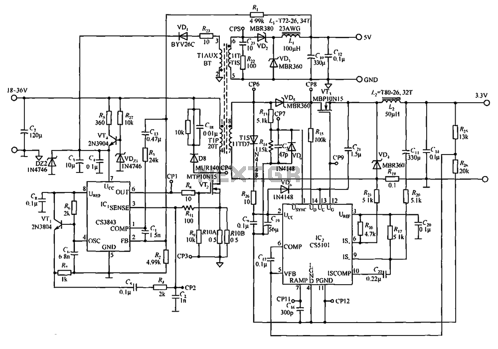
The CS3843 and CS5101 are components of a 5V/3.3V switching DC power supply circuit. The CS3843 is a fixed frequency PWM controller characterized by a set oscillator that precisely controls the duty cycle. It features a temperature-compensated reference voltage,...
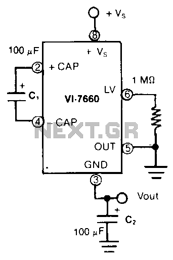
In this application, the VL-7660 is configured as a voltage splitter. The normal output pin is connected to ground, while the normal ground pin serves as the output. The switches facilitating charge pumping are bidirectional, allowing for reverse charge...
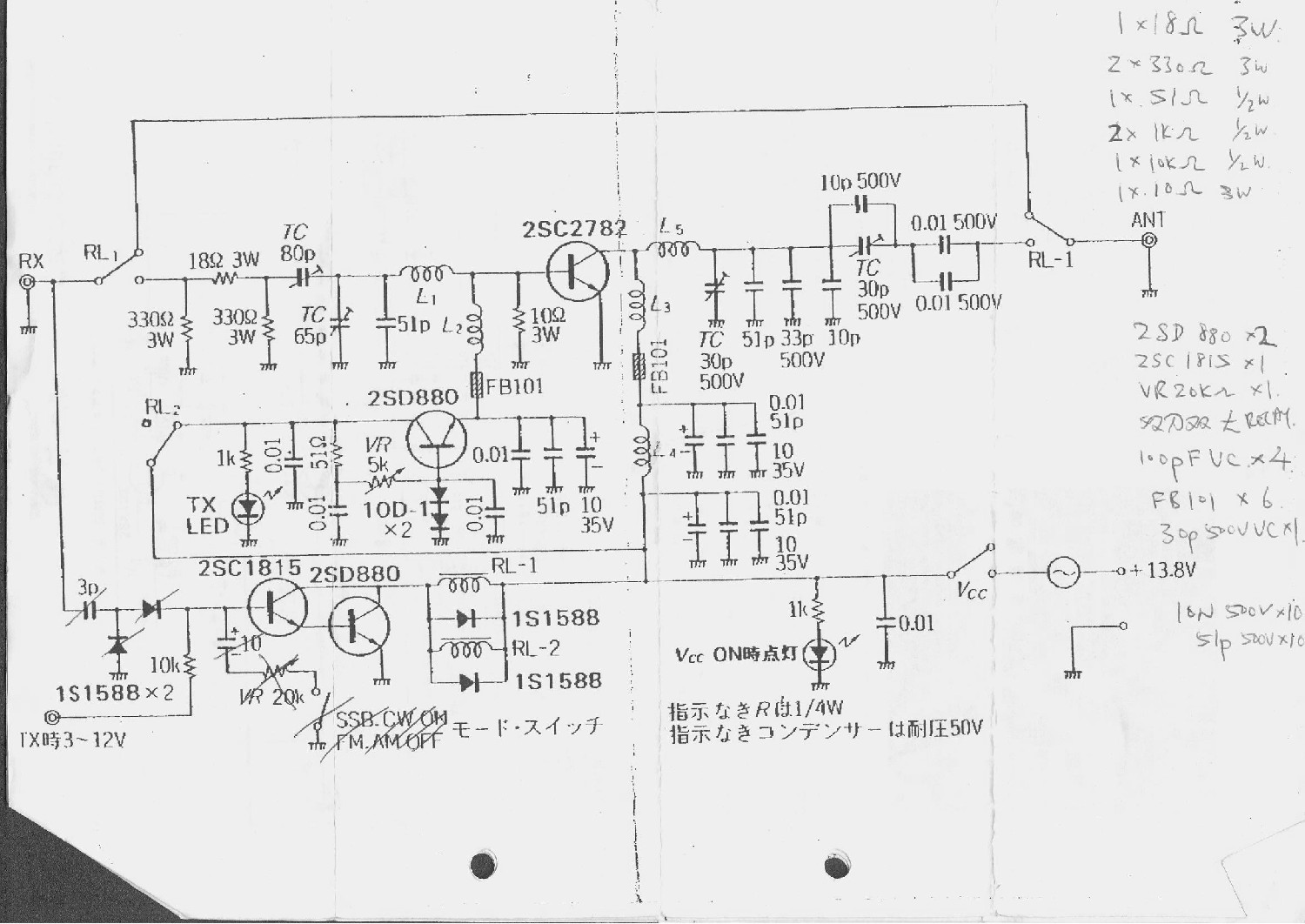
This is a 6-meter band transmitter RF power amplifier (50 MHz) with a 100W output. It is compatible with the FT-736R and is driven by a 10W signal for 6m SSB DX. The construction information is sourced from Japan...
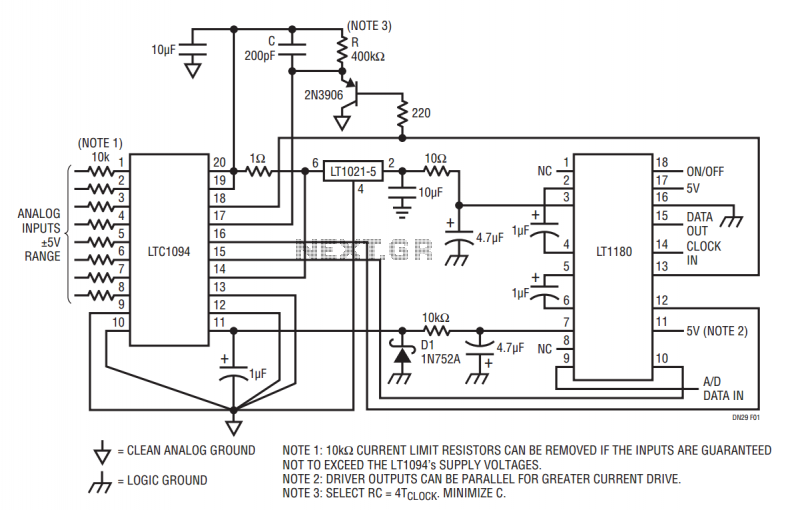
The LT1180 RS232 transceiver includes a charge pump which produces low ripple supplies with sufficient surplus current to drive a CMOS A to D converter and precision voltage reference. The circuit operates from a single 5V supply and draws...