
Practical loudness control circuit

The loudness volume control circuit depicted in Figure 1-91 serves as an essential component in audio amplification systems, facilitating enhanced sound quality by allowing users to adjust the bass response according to their preferences. The integration of this circuit into the preamplifier stage ensures that the audio signal is processed with minimal distortion, providing a clean output even at higher volumes.
The use of an emitter current source in the preamp output stage is crucial, as it stabilizes the output impedance, allowing for better interaction with subsequent audio stages. The adjustable operating current between 4 to 6 mA is a notable feature, as it caters to various load conditions while ensuring that the signal level remains robust. This flexibility is particularly beneficial in diverse audio environments where load characteristics may vary.
The implementation of a FET for the loudness control is advantageous due to its high input impedance, which minimizes the loading effect on the preceding circuit. This design choice also contributes to a lower noise figure, enhancing the overall audio fidelity. The inclusion of high-frequency compensation is vital for maintaining a balanced audio output, particularly in systems where treble frequencies may be underrepresented. By allowing for resistance adjustments, the circuit provides users with the ability to fine-tune the compensation level, ensuring optimal performance across a wide range of audio inputs.
In summary, the loudness volume control circuit is a sophisticated solution for enhancing audio quality in preamplifier applications, characterized by its low distortion, high input impedance, and customizable compensation features. This design not only improves the listening experience but also integrates seamlessly into existing audio systems, making it a valuable addition for audiophiles and audio engineers alike.Figure 1-91 is added loudness volume control circuit practical circuit. It plugs into the preamp and tone control circuit of the room, behind the OCL and other can be connected to the main amplifier. Practical effect proved effective. In volume was very hour, can get a clear, soft bass o preamp output stage uses emitter-current source, thus ensuring a very low output impedance and good follow-up characteristic. Its operating current adjusted between 4 ~ 6mA, under load is small, it can also have a sufficient signal level outputs, and to ensure minimum distortion (when the volume is zero, the load on the preamplifier lower resistance Ri) o after loudness with the volume control FET, a high input impedance and low noise figure.
The circuit plus the high end of the compensation, lack of treble if used according to the dashed line in Fig added high-frequency compensation, adjusting the resistance in order to change the compensation level.
Related Circuits
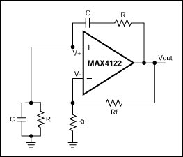
This application note explains how the transfer function of most operational amplifier circuits can be derived through a straightforward process of nodal analysis. The transfer function of operational amplifier (op amp) circuits is a critical aspect for understanding their behavior...
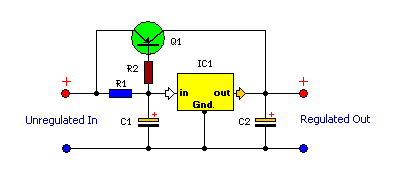
This is a compact and highly functional circuit that can be constructed on a veroboard. Voltage regulators such as the LM708 and LM317 series (among others) may occasionally require a load. The circuit utilizes voltage regulators, which are essential components...

The LT6552 is a video difference amplifier optimized for low voltage single supply operation. The LT6552 features a 75MHz 3dB bandwidth, a 600V/µs slew rate, and ±70mA output current, making it ideal for driving cables directly. This circuit maps...
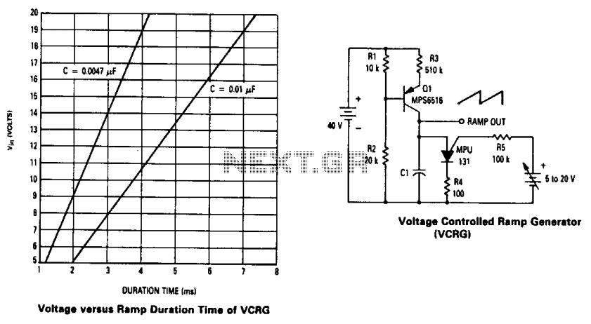
The current source created by Q1 in combination with capacitor C1 determines the duration of the ramp. As the positive DC voltage at the gate varies, the peak point firing voltage of the Programmable Unidirectional Thyristor (PUT) is altered,...
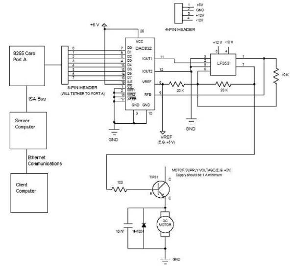
Open loop speed control of a DC motor is implemented using the 8255 Digital I/O Controller chip in conjunction with a TCP/IP server-client application programmed in Visual Basic. The DAC0832 chip serves as the Digital to Analog Converter. This...
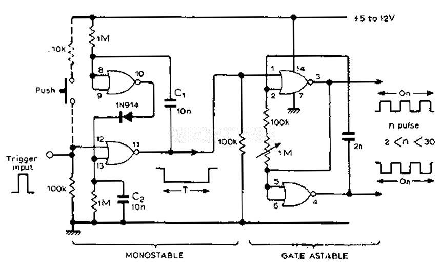
Each trigger input can produce a fixed number of pulses, with the range being from 2 to 30. The specific number is determined by the frequency-controlled settings of 1 megohm. A monostable gated unsteady power supply circuit can be...