
PWM Speed Rotation Forard-Reverse and Regenerative Braking

The PWM speed control circuit for a DC motor is designed to provide versatile operation, including both forward and reverse functionalities along with regenerative braking. The core of the circuit employs a power MOSFET, specifically the IRF150, which is capable of handling significant current and voltage, making it suitable for controlling a 12V DC motor effectively.
The PWM signal is generated by a microcontroller or a dedicated PWM generator circuit, which modulates the duty cycle to adjust the speed of the motor. A higher duty cycle corresponds to a higher average voltage supplied to the motor, resulting in increased speed, while a lower duty cycle reduces the speed.
Relay RY1 is crucial for enabling reverse rotation. It is activated by a digital alarm system that can signal when a direction change is necessary. The inclusion of a changeover switch, Q10, allows for seamless switching between forward and reverse operations without mechanical wear.
Relay RY2 serves a dual purpose; it functions as a brake resistor during regenerative braking. When the motor is decelerated, the energy generated is dissipated through this resistor, preventing back EMF from damaging the circuit components. This regenerative braking feature enhances energy efficiency by converting kinetic energy back into usable electrical energy.
Fuse F1 is incorporated into the design to provide overcurrent protection, ensuring that the circuit remains safe from potential short circuits or overload conditions. Diode D1 is strategically placed to prevent reverse current flow from the motor back into the control circuit, safeguarding sensitive components from damage.
Overall, this PWM speed control circuit is a robust solution for controlling DC motor speed and direction while incorporating essential safety features and regenerative braking capabilities. Further analysis of the circuit diagram will yield additional insights into the specific connections and component values used in the design.This is PWM Speed DC motor Rotation circuit. It can Forard-Reverse and Regenerative Braking function. By this circuit use a signal PWM control the speed of DC 12V motor with Power mosfet IRF150. The relay RY1 use control Reverse with the digital alarm, change, Q10. The Relay RY2 work be, function brake resistor. By control Run or stop with the digital alarm with. The F1, use protect through the circuit. The D1 use for protect current turn back from DC Motor. The detail is other, please see in the circuit. Disclaimer All files are found using legitimate search engine techniques. This site does not and will not condone hacking into sites to create the links it list. We will and do assume that all links found on the search engines we use are obtained in a legal manner and the webmasters are aware of the links listed on the search engines. If you find a URL that belongs to you, and you did not realize that it was "open to the public", please use the report button to notify the blogmaster of your request to remove it or it will remove within 24 hours.
This is not an invitation for webblog haters to spam with requests to remove content they feel that is objectionable and or unacceptable. Proof of URL ownership is required. NOTICE: This Blog Has Already Been Reviewed And Accepted By Blogger. com 🔗 External reference
Related Circuits
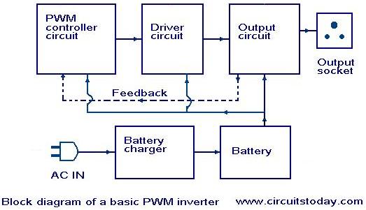
Nowadays, most inverters available in the market utilize Pulse Width Modulation (PWM) technology. Inverters based on PWM technology exhibit superior performance in several aspects compared to those designed using conventional methods. These PWM inverters typically employ MOSFETs in the...
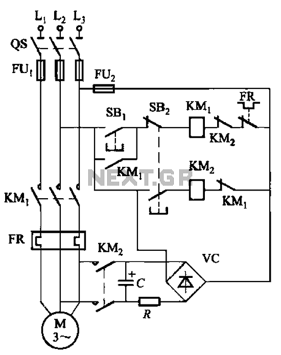
The circuit depicted in Figure 3-138 utilizes the principle of energy storage through capacitor discharge to achieve braking. The capacitance (C) and resistance (R) parameters are determined based on the size of the motor power. The capacitance (C) is...
PWM waveforms are frequently employed to regulate the speed of DC motors. The mark/space ratio of the digital waveform can be established either by utilizing an adjustable analog voltage level (as seen in a NE555-based PWM generator) or through...
For normal use it is necessary to connect the battery when the jumper is connected. Please take care that the transmitter is on and the throttle is set to "power off". More: * switch on the transmitter, throttle to...
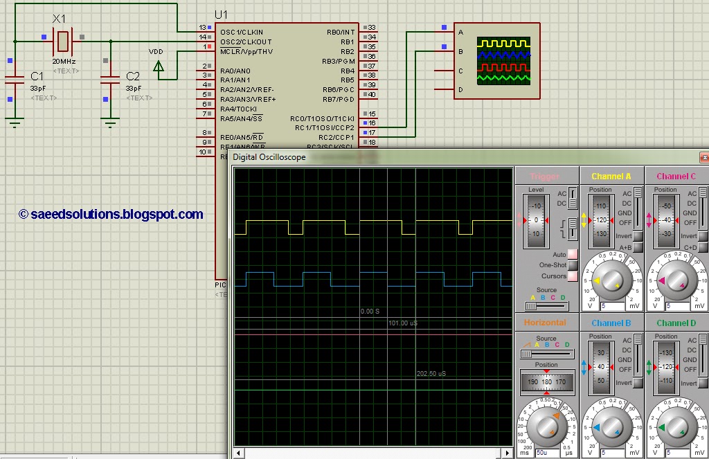
This post addresses the question, "How to create a pulse width modulator using the PIC16F877?" Additionally, the PWM code can be verified using the PIC16 simulator (Proteus). The PIC16F877 microcontroller is widely utilized for creating pulse width modulation (PWM) signals...
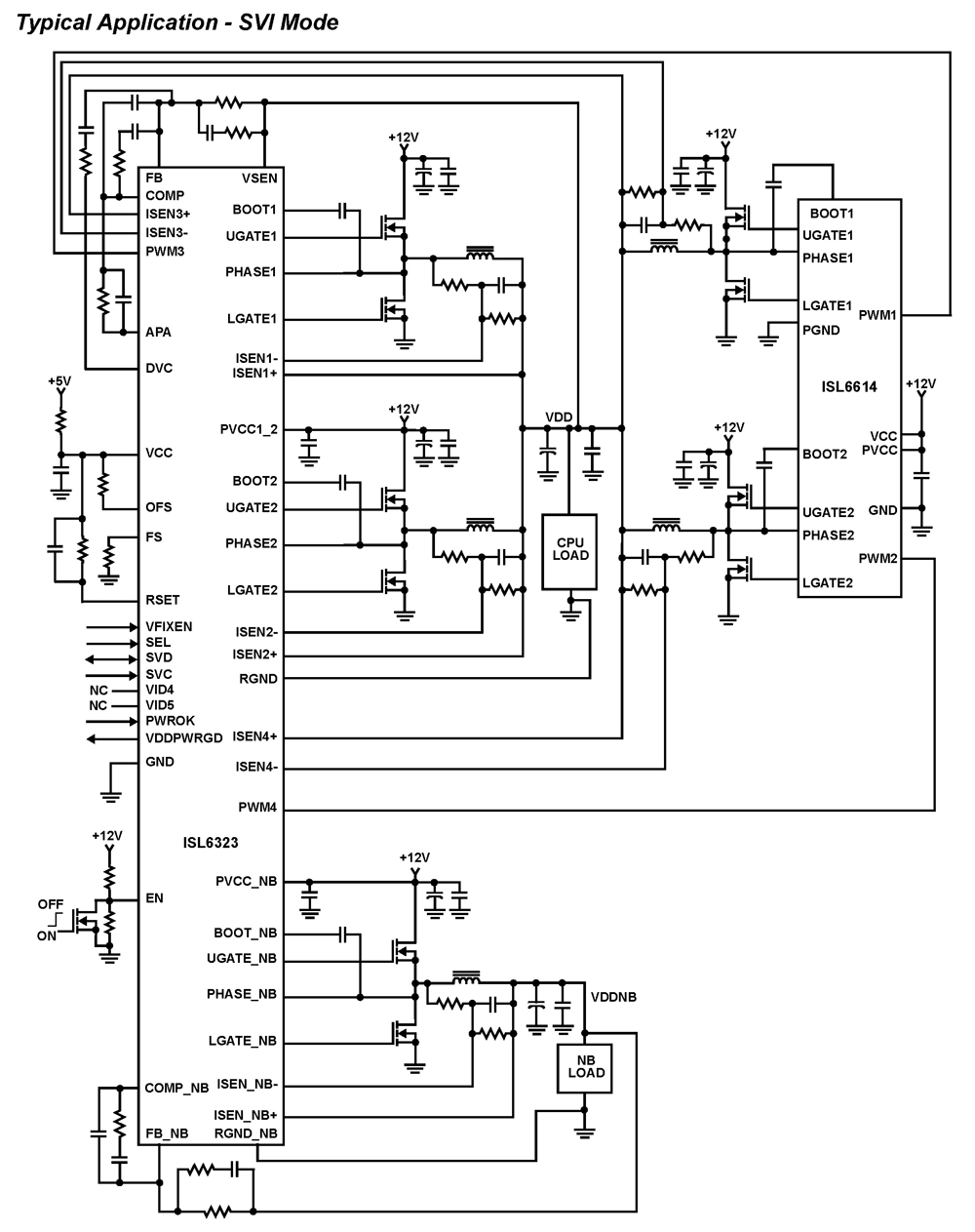
The ISL6323 dual PWM controller provides high efficiency and precise regulation through two synchronous buck DC/DC converters. It supports hybrid power control for AMD processors, operating via either a 6-bit parallel VID interface (PVI) or a serial VID interface...