
Radio Beacon Converter

The radio beacon system operates within a specified frequency range, facilitating the transmission of Morse-coded callsigns for identification purposes. The band-pass filter serves a dual role: it not only filters out unwanted signals but also matches the impedance levels between the aerial and the mixer IC1, ensuring efficient signal processing. The mixer circuit is crucial as it shifts the frequency of the incoming beacon signal to a range compatible with standard shortwave receivers. This frequency conversion is essential for practical reception, as the original beacon frequencies are not directly accessible by typical shortwave equipment.
The design of the circuit includes specific considerations for shielding sensitive components, which is vital for minimizing electromagnetic interference and ensuring stable operation. The alignment process is critical for achieving optimal performance. By utilizing an SSB receiver, the user can fine-tune the oscillator frequency to achieve a zero beat condition, which indicates that the local oscillator and the incoming signal are in phase, maximizing the signal strength. The subsequent detuning process allows for the identification of the beacon signal, which can be adjusted for clarity and volume, ensuring that the output is not only audible but also of high quality.
In summary, this radio beacon receiver circuit exemplifies a well-engineered solution for receiving and decoding Morse-coded signals from distant beacons, incorporating essential filtering, impedance matching, and alignment techniques to enhance performance and usability within the designated frequency range. The radio beacon band extends from 280 to 516 kHz. Each beacon has its own characteristic AM"-modulated morse-coded callsign that is transmitted on a specific frequency. To be able to receive distant beacons, the aerial signal is passed through a band-pass filter that effectively suppresses longwave and mediumwave signals. The filter also converts the aerial impedance, Zm, from about 10 KOhmhm to the input impedance of mixer IC1, which is about 1 KOhmhm.
The mixer adds or subtracts the received signal to/from the local oscillator signal so that the beacon signal can be received on a normal shortwave receiver. The resulting frequencies are from 9.72 to 9.48 MHz or from 10.280 to 10.516 MHz. In the construction of the converter, some components must be surrounded by a metal shield, as indicated by dashed lines on the PC board layout.
The circuit is aligned with the aid of an SSB receiver, to which the output of the converter is connected. Tune the receiver to 10 MHz and adjust the oscillator frequency of the converter with C8 for zero beat.
Next, detune the receiver slightly until you hear a pleasant whistle, which is adjusted for minimum level with the aid of PI. Finally, tune to a beacon transmitting at or about 300 kHz and adjust C13 for maximum sound output.
Related Circuits
The ADF4107 Frequency Synthesizer can be used to implement local oscillators in the upconversion and downconversion sections of wireless receivers and transmitters. It consists of a low noise digital phase frequency detector (PFD), a precision charge pump, a programmable...
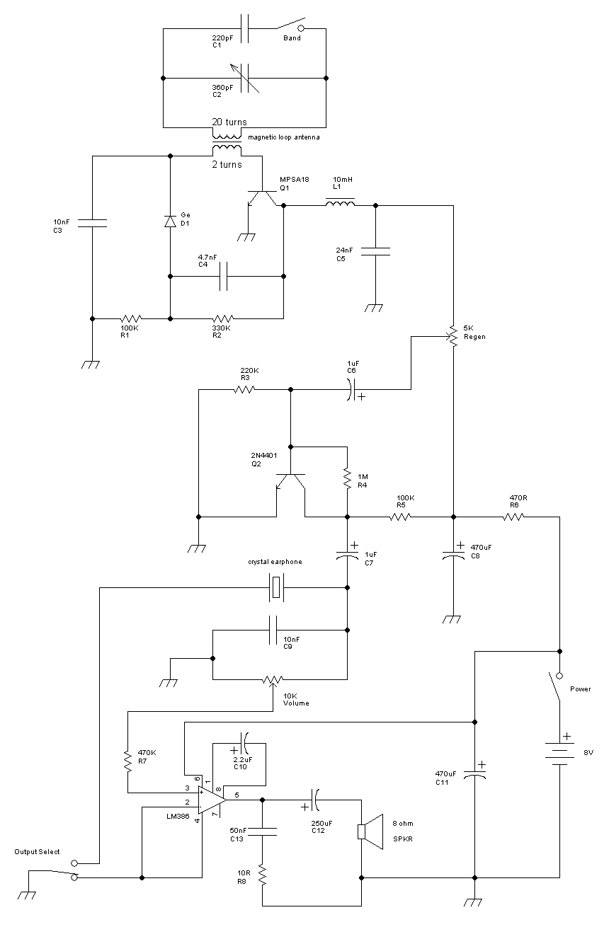
This receiver is a modification of Charles Wenzel's Two Transistor Reflex Radio. Instead of a ferrite AM loopstick antenna, a magnetic loop antenna is used, and an LM386 amplifier stage has been added to drive an 8-ohm speaker. A...
When the weather is hot and the sun is shining, the car fails to start, and the radio, keyless entry, power windows, power locks, and power seats do not function. However, after sunset, everything operates normally. It is important...

This is a simple interface box designed to connect a radio to a PC, featuring several enhancements compared to similar projects widely available. Such interfaces are utilized to manage the transmission and reception of digital signals (RTTY, BPSK, and...
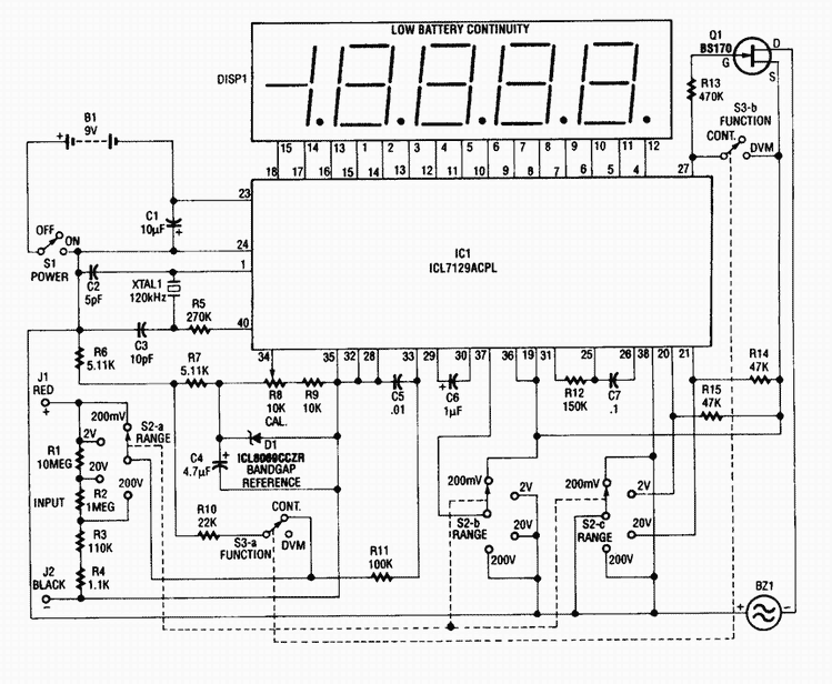
This 4 1/2-digit DVM circuit is built around a Maxim ICL7129ACPL A/D converter and LCD driver. An ICL8069 CCZR 1.2-V band-gap reference diode is used for a voltage reference. S2a-b-c select one of four ranges up to 200 V...
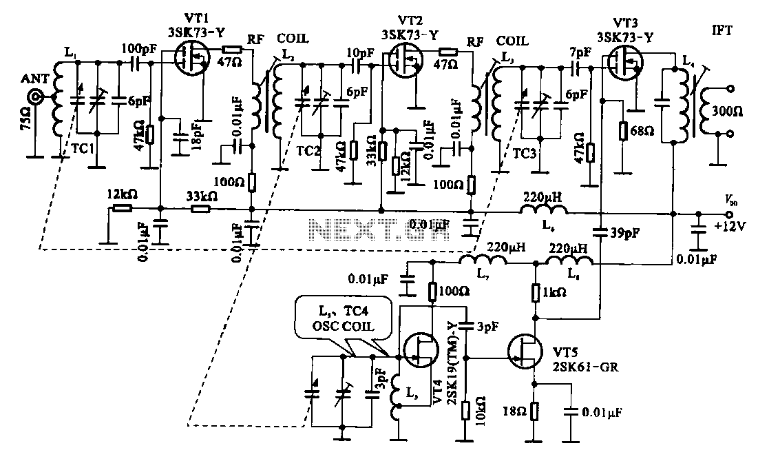
The FM radio circuit is represented by a double-gate MOS field-effect transistor. The high-frequency amplifier is a bipolar MOS field-effect transistor amplifier consisting of transistors VT1 and VT2. VT3 serves as the mixer. The local oscillator is formed by...