
Rain detector electronic circuit project

The rain detector circuit operates by utilizing two transistors configured in a feedback loop to create an oscillator. The sense pad, which is the primary sensing element, is designed to detect the presence of liquid. It can be fabricated using conductive materials on a printed circuit board (PCB) to ensure proper sensitivity and reliability.
Upon contact with liquid, the sense pad completes the circuit, allowing current to flow through Tr1 and Tr2. This leads to the generation of an oscillating signal that drives a connected speaker, producing an audible alarm. The frequency of the oscillation can be adjusted by changing the values of the resistors and capacitors in the circuit, thereby allowing customization of the pitch of the sound emitted.
The power supply for this circuit is specified at 12 volts, which is standard for many electronic applications, ensuring compatibility with various power sources. The choice of a 32-ohm speaker is critical for achieving optimal sound output, as it matches the circuit's output characteristics and ensures efficient energy transfer.
In summary, this rain detector circuit is an effective and straightforward solution for alerting users to the presence of rain or liquid. Its design simplicity, combined with the ability to customize sound output, makes it suitable for various applications, including home automation and weather monitoring systems.This rain detector electronic circuit project is an very simple alarm circuit, that will start an audio warning, if the liquid is present on the sense pad. This rain detector electronic circuit diagram is based on two transistors. When the sense pads conducts, Tr1 and Tr2 from an audio oscillatory circuit that will generate a pitch sound.
Th is circuit needs a 12 volts power supply circuit and the speaker needs to have a 32 ohms. The sense pad can be constructed on a small piece of printed circuit board. 🔗 External reference
Related Circuits

Originally, the tank cost around Php 400 but was later sold for approximately a hundred pesos less. Recognizing a great deal, the decision was made to purchase the toy. Opening the toy proved to be somewhat challenging. The track...
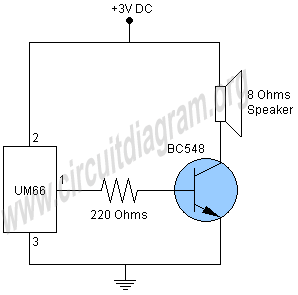
This project involves a simple doorbell circuit featuring the UM66 melody integrated circuit (IC), which is well-known for its melody generation capabilities. The IC is housed in a TO-92 transistor package and consists of only three pins, functioning as...

The LM555 timer IC can be utilized in various electronic projects, including the creation of an analog timer. According to the datasheet, the LM555 is versatile and can be adjusted to set timers based on specific requirements. The schematic...
This continuous wave (CW) transmitter is capable of producing an output power of up to 3 watts. By applying a 24-volt supply to transistor Q2, the output power can be increased to as much as 10 watts. It is...
This portable mobile transmission detector can detect the presence of an activated mobile phone from a distance of 1.5 meters. It is designed to prevent the use of mobile phones in examination halls, confidential areas, and other restricted environments....

The LM2002 / 2002A is an audio power amplifier integrated circuit. The LM2002A features high voltage protection, with a maximum instantaneous power supply voltage of up to 40V, and comes in a 5-pin single in-line plastic package. This integrated...