
Rain Sound Generator Using NE555 PCB

The timer 555-based rain sound generator circuit employs a combination of a UJT relaxation oscillator and a 555 timer IC to create a realistic rain sound effect. The UJT (uni-junction transistor) acts as the primary frequency generator, producing a square wave oscillation that is dependent on the selected capacitance value of capacitor C1 and the characteristics of the 2N2646 transistor. This oscillator's output is crucial as it directly influences the operation of the NE555 timer by continuously resetting it, ensuring that the timer is in a state of constant oscillation.
The NE555 timer is configured in astable mode, which allows it to produce a continuous square wave output. The frequency of this output can be adjusted by varying the resistor and capacitor values connected to the timer. The output from the NE555 is then fed into the connected speaker, which converts the electrical signals into audible sound waves. The combined effect of the UJT oscillator and the 555 timer creates a sound that mimics the gentle patter of raindrops, making the circuit ideal for sound effects in various applications.
Powering the circuit with a 9V battery provides sufficient voltage for both the UJT and the NE555 timer to function effectively, while the 0.5W, 8-ohm speaker is capable of producing the required sound output without distortion. This circuit can be further enhanced by incorporating additional components such as filters or tone control to refine the quality of the sound produced, thereby allowing for customization based on user preferences. Overall, this rain sound generator circuit serves as an excellent example of utilizing basic electronic components to achieve a specific auditory effect.The circuit diagram shows a timer 555 based rain sound generator. The circuit requires a 9V dc power supply and can be fed from a 9V battery. The loud speaker for producing sound is of 0. 5W 8ohm speaker. The circuit will readily generate a rain like sound whenever the circuit fed by a 9V supply. The rain generator has two sections one is a UJT rela xation oscillator. This oscillator is build upon the uni junction transistor 2N2646. This oscillator produces a fixed frequency as per the value of C1. This continuously resets the 555 because the UJT oscillator output is connected to the reset pin of the NE555. On the other hand, the 555 IC works itself as a astable multivibrator. This process result in the generation of a rain like sound from the speaker. 🔗 External reference
Related Circuits
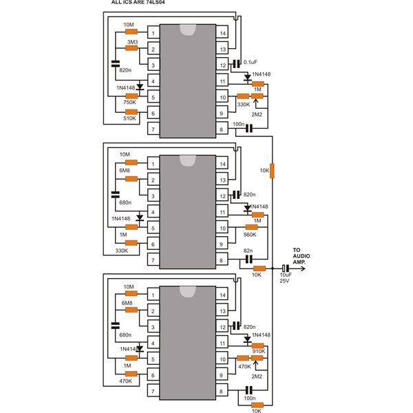
This document discusses a compact machine gun sound effect generator circuit. Once constructed, it can be integrated with any audio amplifier to create a realistic war-like simulation. This small hobby project is suitable for all electronics enthusiasts and generates...
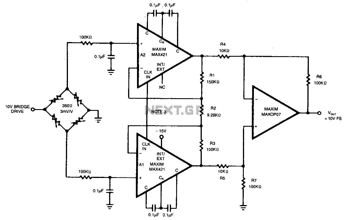
This circuit achieves an overall gain of 320. Additional gain can be obtained by decreasing the value of R2. The untrimmed Vas is 10.11V, and the Vas temperature coefficient is less than 0.1µV/°C. In various applications, the OP07 can...
This circuit detects the dial tone from a telephone line and decodes the keypad pressed on the remote telephone. The dial tone heard when picking up the phone is referred to as Dual Tone Multi-Frequency (DTMF). This name originates...
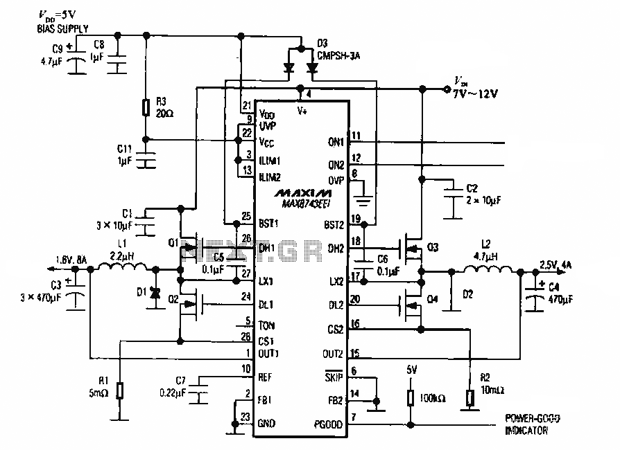
The circuit utilizes the MAX8743 chip for a laptop chipset power supply. It demonstrates the conversion of a 5V power supply into +2.5V and +1.8V outputs. The MAX8743 is a highly integrated power management solution designed specifically for laptop chipsets....
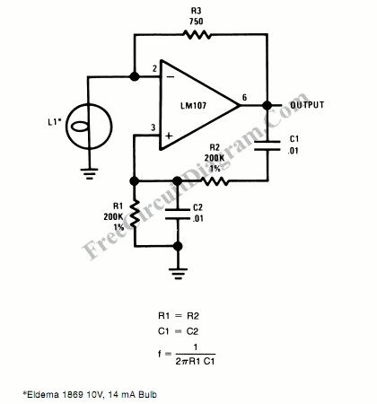
An incandescent lamp has been utilized to reduce harmonic distortion in a sine oscillator circuit. The nonlinear resistance characteristic of the lamp filament assists in this process. In the context of electronic circuits, the use of an incandescent lamp as...
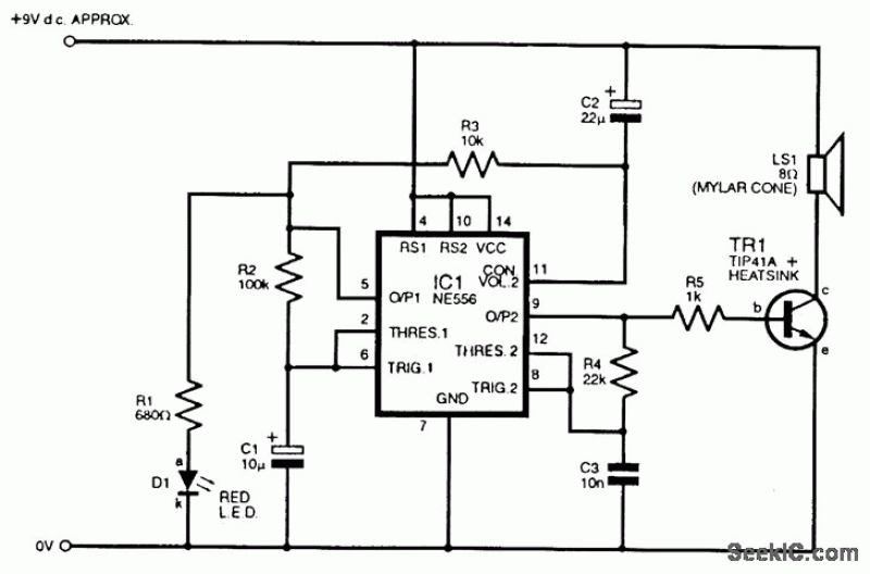
An adaptable siren generator circuit with multiple applications is presented. It is based on a 556 twin-timer chip, IC1. One timer section generates an audio tone that is directly coupled to the driver transistor, TR1. The other half of...