
Relation to Classic Oscillator Theory

The open-loop oscillator design is a fundamental concept in RF circuit design, often challenging the traditional views held by engineers. The use of RF components in the design is critical, as shown in the initial representation (Figure 2-4A), which highlights their role in the oscillator cascade. By connecting the output back to the input while floating the ground (Figure 2-4B), the circuit exhibits unique feedback characteristics that are essential for oscillator functionality.
In the subsequent illustrations, the choice of ground reference significantly influences the oscillator type. When the emitter is designated as the ground reference (Figure 2-4C), the circuit operates as a common-emitter Pierce oscillator. This configuration is notable for its simplicity and effectiveness in generating stable oscillations, making it a popular choice in various applications.
Conversely, when the base is selected as the ground reference (Figure 2-4D), the circuit transitions to a common-base Colpitts oscillator. This variant is characterized by its high-frequency performance and is often utilized in applications requiring low noise and high stability.
The realization that these open-loop configurations—Pierce and Colpitts—are fundamentally the same oscillator is crucial for engineers. It underscores the versatility of oscillator design and the importance of understanding the underlying principles that govern their operation. This knowledge allows for more efficient design choices in RF applications, leading to optimized performance and reliability in electronic systems.The open-loop concept of oscillator design is often met with considerable skepticism by engineers familiar with classic oscillator terminology. For comfort consider Figure 2-4A where the oscillator cascade is drawn with only the RF components. Next, the circuit is redrawn in Figure 2-4B with the output connected to the input and the ground floated
. In Figure 2-4C the emitter is selected as the ground reference point. Notice the configuration is the familiar common-emitter Pierce oscillator. In Figure 2-4D the circuit is again redrawn, this time with the base selected as ground reference. The result is the familiar common-base Colpitts. These open-loop, Pierce and Colpitts oscillators are in fact the same oscillator! 🔗 External reference
Related Circuits

This is a 100 MHz Varicap Oscillator circuit. This circuit can provide modulation signals of less than 28 V and a frequency deviation of 28 MHz peak-to-peak. The 100 MHz Varicap Oscillator circuit is designed to generate high-frequency signals suitable...
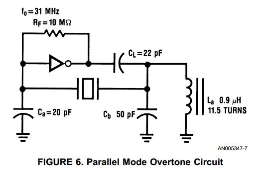
With the advent of high speed HCMOS circuits, it is possible to build systems with clock rates of greater than 30 MHz. The familiar gate oscillator circuits used at low frequencies work well at higher frequencies and either LC...
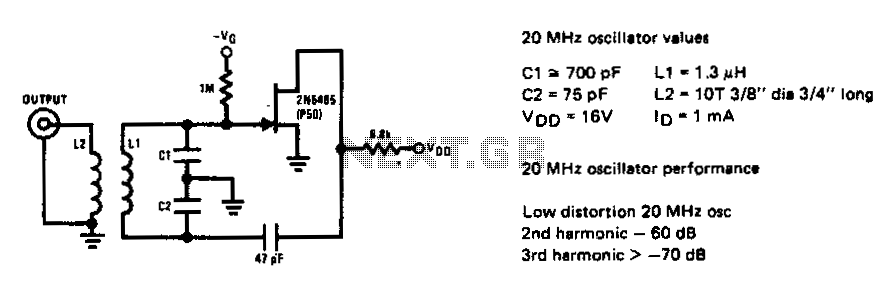
The 2N5485 JFET can oscillate in a circuit with very low harmonic distortion. This JFET local oscillator is ideal when low harmonic content is needed for an effective mixer circuit. The 2N5485 is a Junction Field Effect Transistor (JFET) that...
An oscillator, a small power stage, some modulation, and a tiny loop antenna make RF for experiments on at 187.5 kHz on the United States' FCC Part 15 Lowfer band (1600-1750 meters). This is a low power signal source...
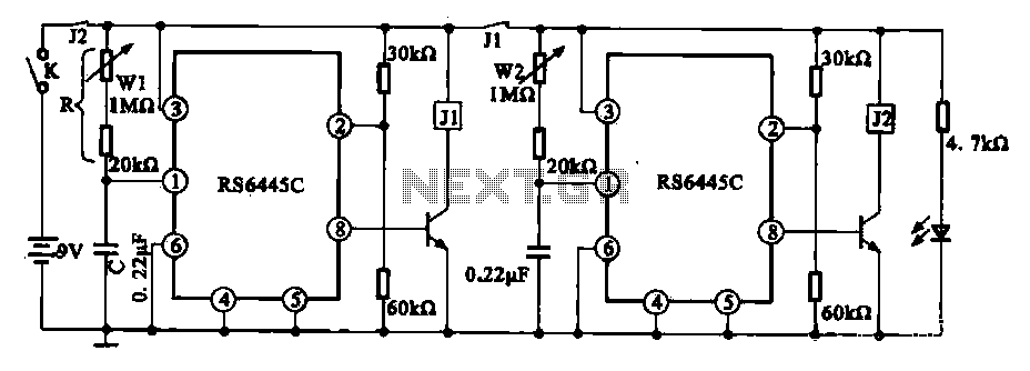
The timing integrated circuit (IC) RS6445C functions as a blocking oscillator. It features two segments, WI and W2, which are utilized to adjust the working time and the closure time. These adjustments can be continuously set within a range...
This CMOS square-wave oscillator utilizes the 4047 multivibrator circuit, suitable for both monostable (one-shot) and astable applications. In the provided configuration, the 4047 operates as an astable multivibrator. The circuit features three outputs from the 4047, with the first...