
Relative Field Strength Meter For A DMM

Passive field strength meters are essential tools used for measuring electromagnetic fields. The design of these meters often incorporates a 50mA analog meter movement, which is a critical component for achieving adequate sensitivity in the measurements. The analog meter movement operates by converting the electromagnetic field strength into a corresponding mechanical movement of the needle, allowing users to visually interpret the field strength levels.
The circuitry of a passive field strength meter typically includes an antenna, which captures the electromagnetic waves. The captured signals are then fed into a rectifier circuit that converts the alternating current (AC) signals into direct current (DC) signals. This rectified output is proportional to the strength of the incoming electromagnetic field.
The analog meter movement is connected to the output of the rectifier, where it translates the DC signal into a readable deflection on the meter scale. The sensitivity of the meter can be adjusted by incorporating resistors or variable potentiometers in the circuit, allowing for calibration based on specific measurement requirements.
In addition to the basic components, passive field strength meters may also include filter circuits to eliminate noise and improve measurement accuracy. These filters can be designed to target specific frequency ranges, enhancing the meter's performance in various applications, such as telecommunications, broadcasting, and RF engineering.
Overall, the design and implementation of passive field strength meters involve careful consideration of component selection and circuit design to ensure reliable and accurate measurements of electromagnetic fields.Many passive field strength meters have appeared in the past, typically using a 50mA analog meter movement if reasonable sensitivity was to be obtained. T.. 🔗 External reference
Related Circuits

This circuit is intended for precision centigrade temperature measurement, with a transmitter section converting to frequency the sensor's output voltage, which is proportional to the measured temperature. The output frequency bursts are conveyed into the mains supply cables. The...
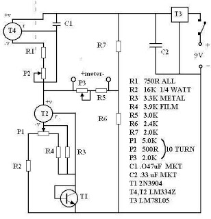
There are many digital thermometers with ±1°C displays, but their accuracy is approximately ±1°C and they cannot be calibrated. A thermometer circuit was created using components available at a local electronics hobby shop, providing an educational experience. For a...
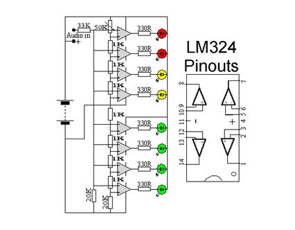
This circuit utilizes two quad op-amps to create an eight LED audio level meter. The op-amp employed in this circuit is the LM324, which is a widely available integrated circuit. The 1K resistors in the circuit are crucial for...
Useful as a transmitter tune-up meter or an RF sniffer, this is an RF field strength indicator that is loosely based on the Broad Band RF Field Strength Probe, described elsewhere. It detects RF via a square law detector,...

This is a circuit for an accelerometer amplifier. It is a straightforward circuit. A precision accelerometer requires an inverting mode amplifier since these devices typically output charge. This amplifier converts charges into a voltage output. The circuit presented below...
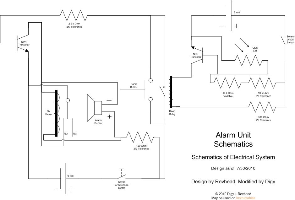
Learn how to strengthen your security system, regardless of its size, with this innovative and customizable laser grid. Once an individual crosses the threshold, the system activates... The concept of a customizable laser grid for security applications involves the deployment...