
relay circuit 9 second led timer

The circuit operates by utilizing a 555 timer configured in monostable mode, which generates a pulse when triggered. The 4017 decade counter is employed to count the pulses from the 555 timer output. Initially, when the switch is closed, the 4017 counter resets, and the first LED lights up, indicating the start of the delay sequence. Each time the 555 timer produces a pulse, the counter increments, lighting up the corresponding LED until the 9th LED is activated.
The timing capacitor of 22µF plays a crucial role in determining the delay duration. The charge and discharge characteristics of this capacitor, in conjunction with resistors connected to pins 2 and 6 of the 555 timer, dictate the timing interval. The output from the 555 timer at pin 3 goes high, signaling the counter to advance. The relay is controlled by the state of pins 11 and 13 of the 4017, which ensure that the relay remains deactivated until the 9th count is reached.
In applications where longer delays are required, increasing the capacitance or resistance will proportionally extend the timing interval. The design of this circuit is straightforward, making it suitable for various applications where a timed relay activation is necessary, such as in lighting systems, automation, and alarm systems. Proper power supply considerations must be made to ensure the reliable operation of the 12-volt relay and associated components.This circuit provides a visual 9 second delay using 10 LEDs before closing a 12 volt relay. When the displace about-face is closed, the 4017 decade adverse will be displace to the 0 calculation which illuminates the LED apprenticed from pin 3. The 555 timer achievement at pin 3 will be aerial and the voltage at pins 6 and 2 of the timer will be a
little beneath than the lower activate point, or about 3 volts. When the about-face is opened, the transistor in alongside with the timing capacitor (22uF) is shut off acceptance the capacitor to activate charging and the 555 timer ambit to aftermath an almost 1 additional alarm arresting to the decade counter. The adverse advances on anniversary absolute activity change at pin 14 and is enabled with pin 13 concluded low.
When the 9th calculation is reached, pin 11 and 13 will be high, endlessly the adverse and animating the relay. Longer adjournment times can be acquired with a beyond capacitor or beyond resistor at pins 2 and 6 of the 555 timer.
🔗 External reference
Related Circuits
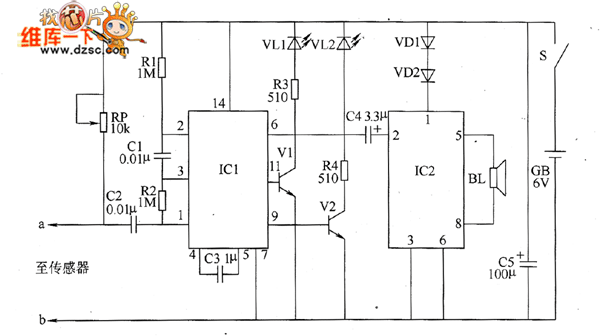
The bearing fault detection circuit comprises bearing detection sensors, a signal processing circuit, and a sound and light circuit. The signal processing circuit includes the input socket XS, a voice integrated circuit IC1, capacitors C1 to C3, resistors R1,...
The telephone line tester comprises a meter used to measure line voltage in both the on-hook and off-hook states, three resistors (including one variable resistor), a pushbutton switch, and a modular telephone connector. When the circuit is connected to...
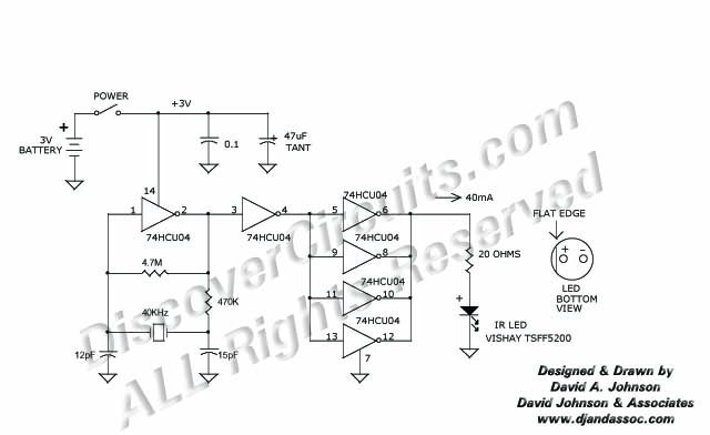
This 40 kHz crystal-controlled oscillator circuit drives an infrared LED with powerful 40 mA pulses. The circuit operates at a frequency of 40 kHz, determined by the crystal oscillator, which provides stable frequency output essential for applications requiring precise timing....
For the shorter wavelength VHF and UHF bands, it is more practical to construct complex antennas such as a single-band Slim Jim or Yagis. Various projects include creating an electronic unit, as it is necessary for the Intermediate Level...
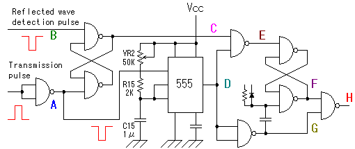
The alarm detector circuit operates differently from the Ultrasonic Alarm (1). In Ultrasonic Alarm (1), an alarm output is triggered by the detection of a reflected wave from an object during the setup time. Conversely, in this circuit, an...
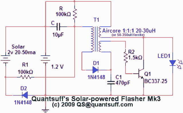
This circuit is a single transistor flyback (Joule Thief) circuit that features a third coil. With it, flash duration and brightness are significantly enhanced. The single transistor flyback circuit, commonly known as a Joule Thief, is designed to efficiently convert...