
Relay Toggle Circuit Using a 555 Timer

The described circuit utilizes a 555 timer in monostable or astable mode to control a relay based on a momentary button press. The configuration leverages the timer's ability to detect voltage levels at its threshold and trigger inputs, which are connected to a voltage divider formed by two 10K resistors. This setup ensures that both pins 2 and 6 are biased at half the supply voltage, providing a stable reference point.
When the button is pressed, it momentarily connects the capacitor (which is typically in the microfarad range) to the trigger input (pin 2). The change in voltage at this pin causes the 555 timer to switch its output state. If the output was previously low, it will go high, energizing the relay coil. This action allows current to flow through the relay contacts, enabling or disabling a connected load.
As the output transitions high, the capacitor begins to charge through the 100K resistor, which controls the charging time constant. The time it takes for the capacitor to charge influences how long the relay remains activated. Once the button is released, the capacitor discharges, and the output will return to its low state, deactivating the relay.
The choice of resistor and capacitor values in this circuit is crucial for determining the timing characteristics and the response of the relay. Additionally, the relay's specifications must be compatible with the 555 timer's output to ensure proper operation without damaging the timer. This circuit can be used in various applications, including automation systems, where momentary control is required.This 555 timer circuit below toggles a relay when a button is pressed. Pins 2 and 6, the threshold and trigger inputs, are held at 1/2 the supply voltage by the two 10K resistors. When the output is high, the capacitor charges through the 100K resistor, and discharges when the output is low.
When the button is pressed, the capacitor voltage is applied to pins 2 and 6 which causes the output to change to the opposite state. When the button is released, the capacitor will charge or discharge to th. 🔗 External reference
Related Circuits
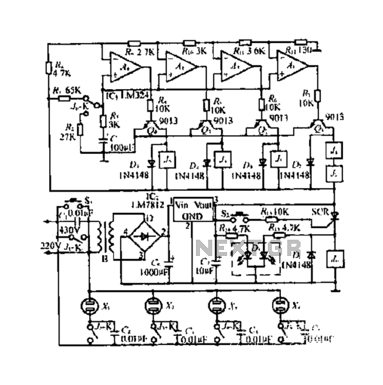
Analyzing the three-phase winding involves examining the head and tail of various therapies, such as the use of hair bundles. The process is simple, safe, and quick. The analysis includes crimping electrical connections, as shown in FIG. 1. The...
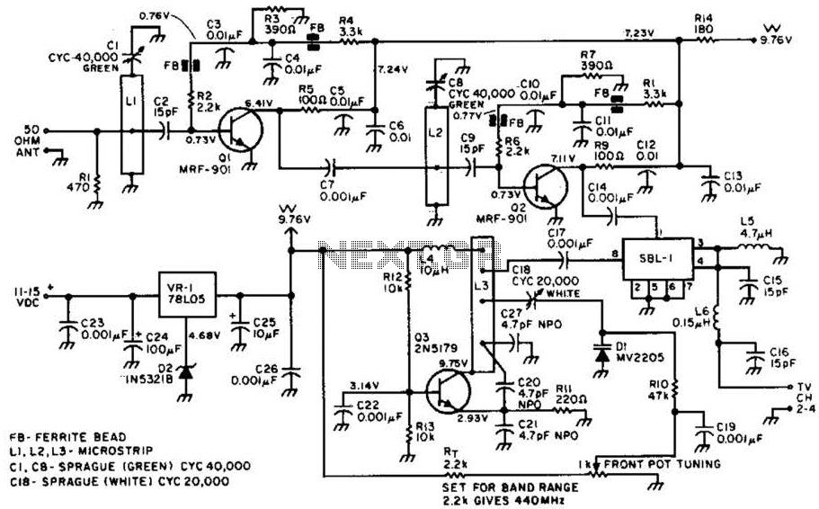
Most ATV (Amateur Television) transmitters operate using a Double Sideband (DSB) signal, while commercial television stations utilize a Vestigial Sideband (VSB) signal. This distinction is leveraged in this converter to utilize the lower sideband, thereby reducing interference from repeaters...
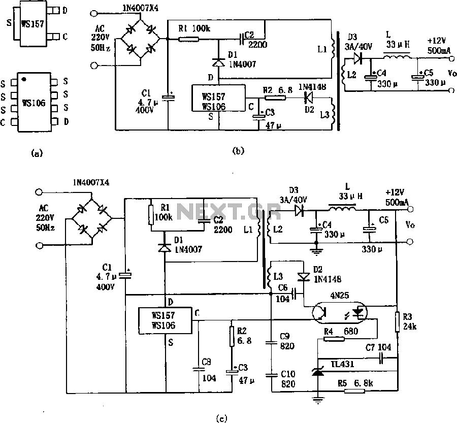
The WS157 or WS106 is a low-power miniature switching power supply that has been developed in recent years. It functions as a regulated switching power supply control device, featuring integrated internal control circuitry and power switches on a single...
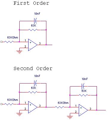
The circuit design involves a circular operational amplifier (op-amp) configuration that functions as a second-order low-pass and high-pass filter. The low-pass filter operates within a frequency range of 20 to 250 Hz, while details regarding the high-pass filter are...

Binu submitted a new resource: Circuit and Program to Interface MT8870 with AT89S51 (version 1.0) - Decoding the DTMF signals from the telephone line. The circuit designed to interface the MT8870 DTMF decoder with the AT89S51 microcontroller is aimed at...
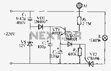
Utilize the call sheet to touch the electrical threshold M, which causes the E lamp to light up. When the same interval subparagraph is triggered, the lights will automatically turn off. A voltage regulator rectifier circuit is formed using...